

Weapon system able to equip a light vehicle and process to implement such a weapon system
- Summary
- Abstract
- Description
- Claims
- Application Information
AI Technical Summary
Benefits of technology
Problems solved by technology
Method used
Image

Examples
Embodiment Construction
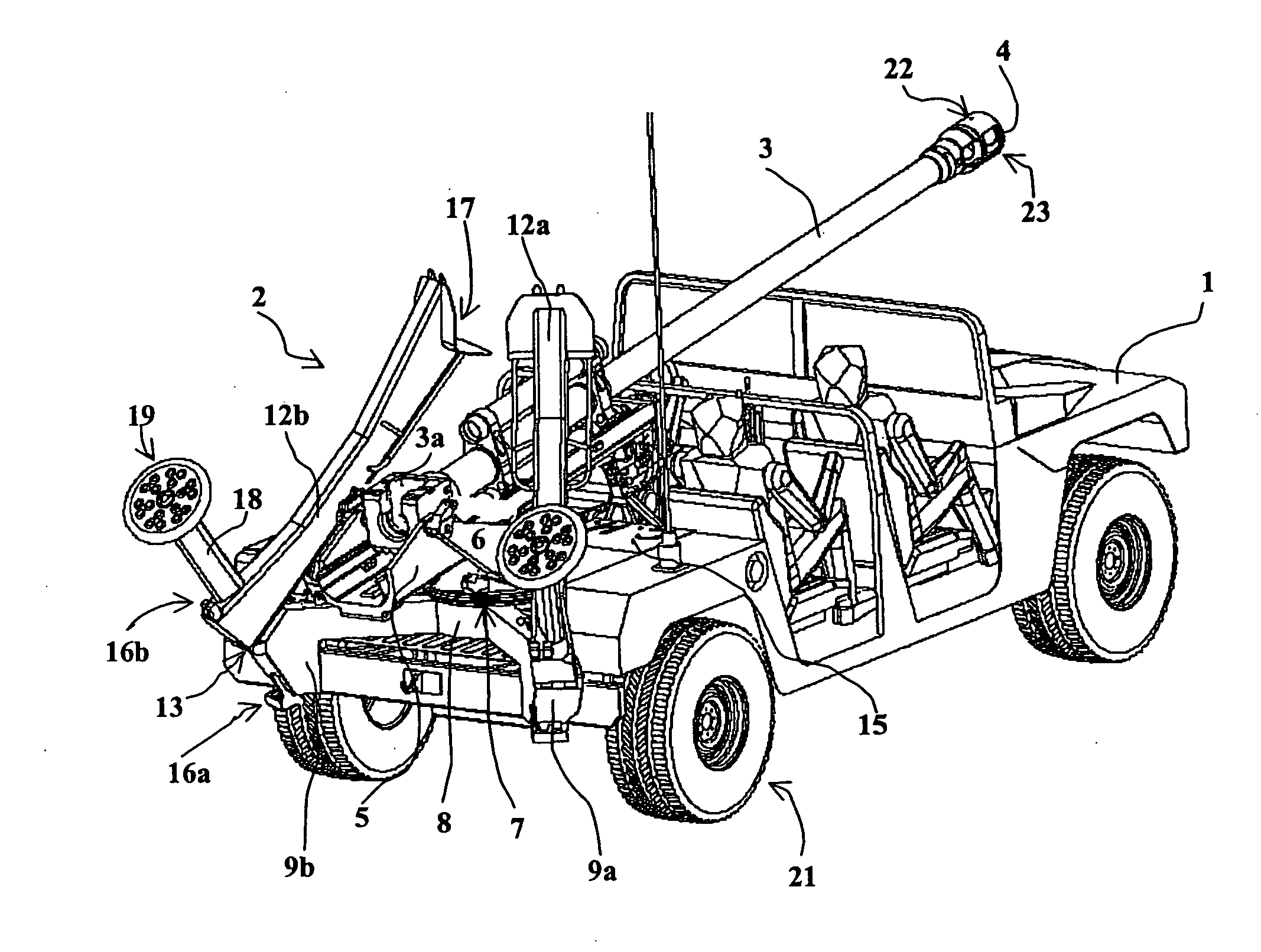
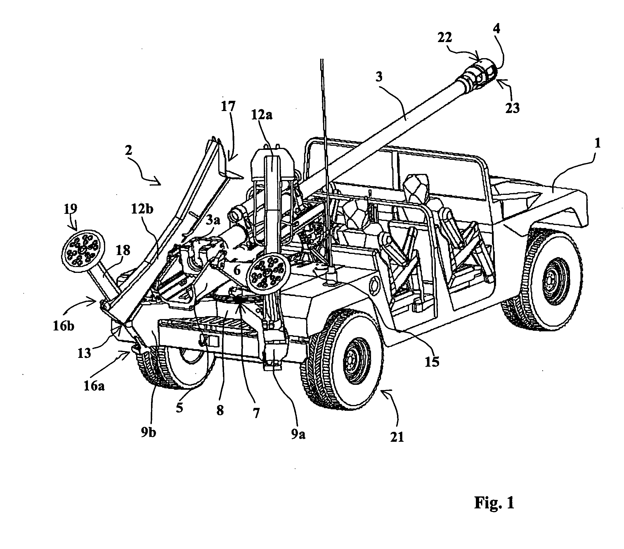
[0034]FIG. 1 shows a rear perspective view of a vehicle 1 equipped with a weapon system 2 according to the invention.
[0035]The vehicle is a light vehicle (mass less than 5 tons), and here it is a 4×4 HMMWV (American Motors registered trademark) whose rear has been emptied out to receive the weapon system.
[0036]The weapon system 2 incorporates a canon 3 equipped with a muzzle brake 4, such cannon mounted on a cradle 5.
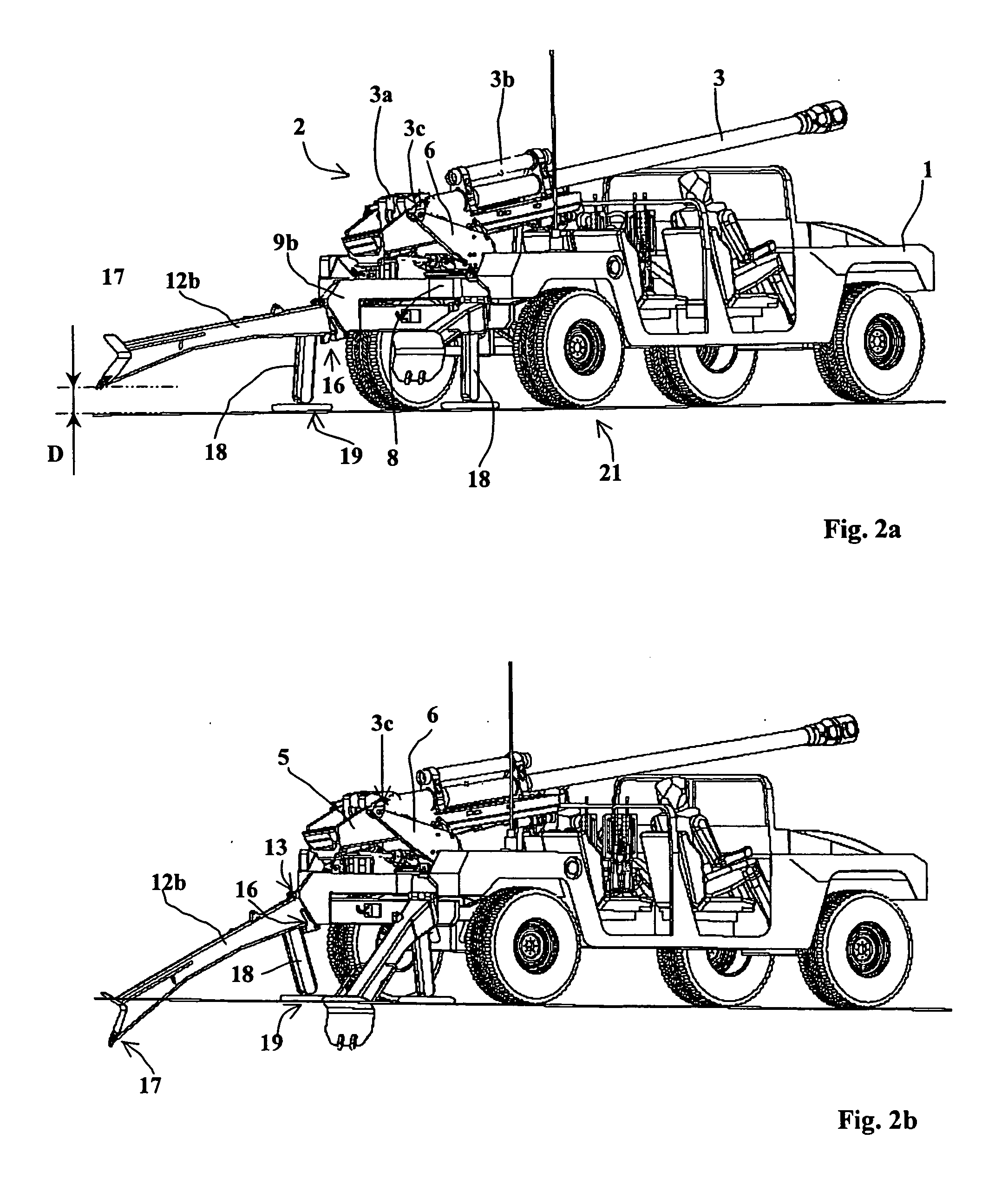
[0037]The structure of the cannon is not the subject of the present invention. The cannon classically comprises a breech ring 3a and a hydraulic recoil brake 3b connecting the cannon to the cradle (see FIG. 2c).
[0038]The cradle 5 is mounted able to pivot around a shaft 3c on a fork 6, thereby enabling the weapon to be laid in elevation. The cradle is classically made to pivot with respect to the fork by an electric motor 24 (see FIGS. 3c and 4).
[0039]The fork 6 is, furthermore, mounted on a turntable 7 (for example with ball bearings) which can be seen more particularly...
PUM
 Abstract
Description
Claims
Application Information