Remote Explosion Detonation System

Inactive Publication Date: 2011-07-21
RAYTHEON CO
View PDF13 Cites 23 Cited by
  • Summary
  • Abstract
  • Description
  • Claims
  • Application Information

AI Technical Summary

Benefits of technology

[0005]Some embodiments of the disclosure may provide numerous technical advantages. For example, one embodiment of the remote explosive detonation system may provide a relatively reliable approach for remotely detonating explosives that reduces detection of the source of the detonation. Known detonation systems use elongated shock tubes that convey a detonation signal using an impulse blast of pressurized air. These shock tubes, however, often leave a residual trail indicating the source of the explosive blast, which may compromise the security of personnel using the explosives. The remote explosive detonation system of the prese

Problems solved by technology

These shock tubes, however, often leave a residual trail indicating the source of the explosive blast, which may compromise the security of personnel using the explosives.
The remote explosive detonation system of the pr

Method used


Image

  • Remote Explosion Detonation System
  • Remote Explosion Detonation System
  • Remote Explosion Detonation System

Examples


Example

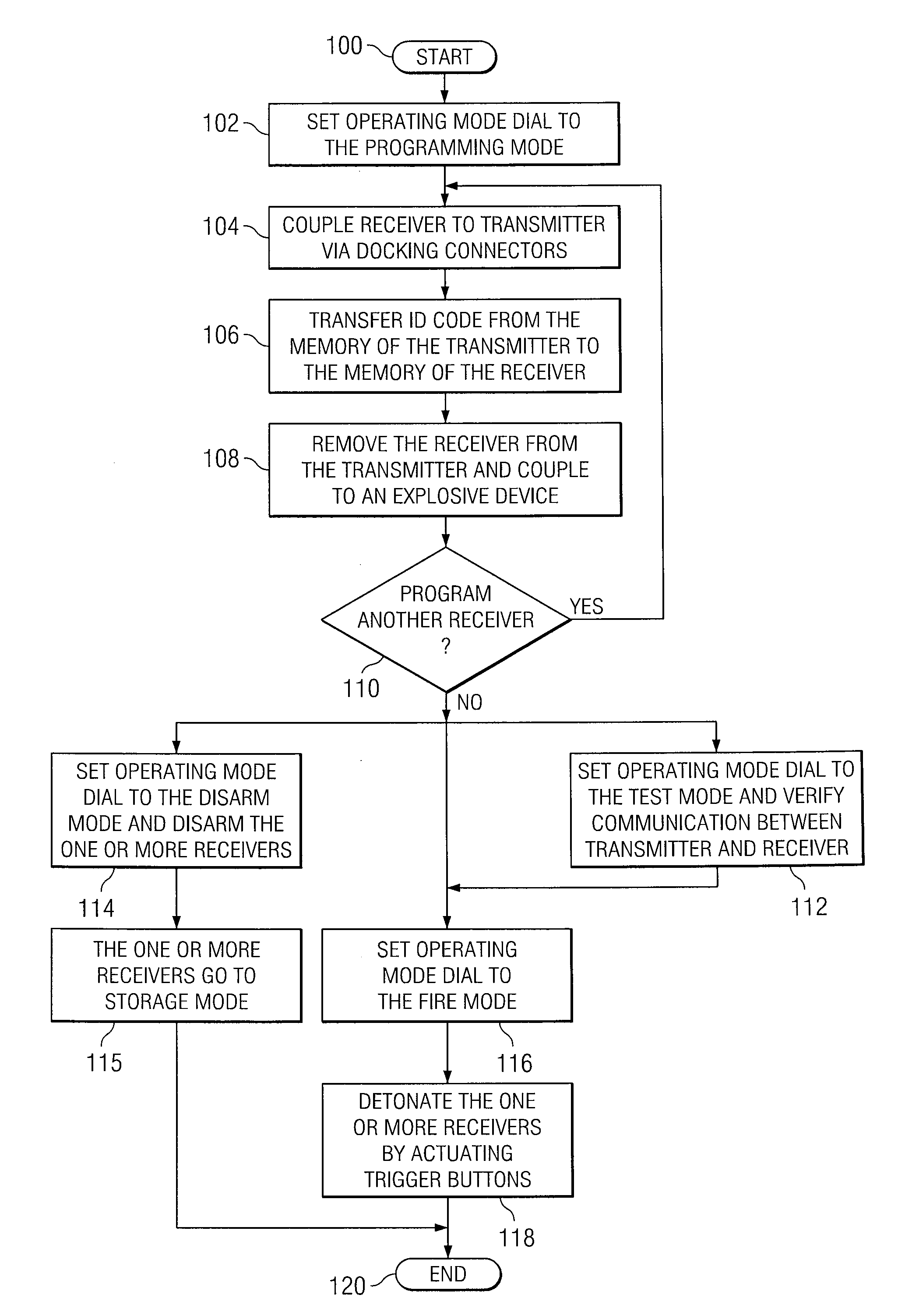
[0015]A shock tube is a detonation device that may be used to detonate an explosive, such as cyclotrimethylene trinitramine (C4). These shock tubes, however, may have drawbacks. For example, following detonation of the explosive, a shock tube may leave a residual trail indicating the location of the triggering device.

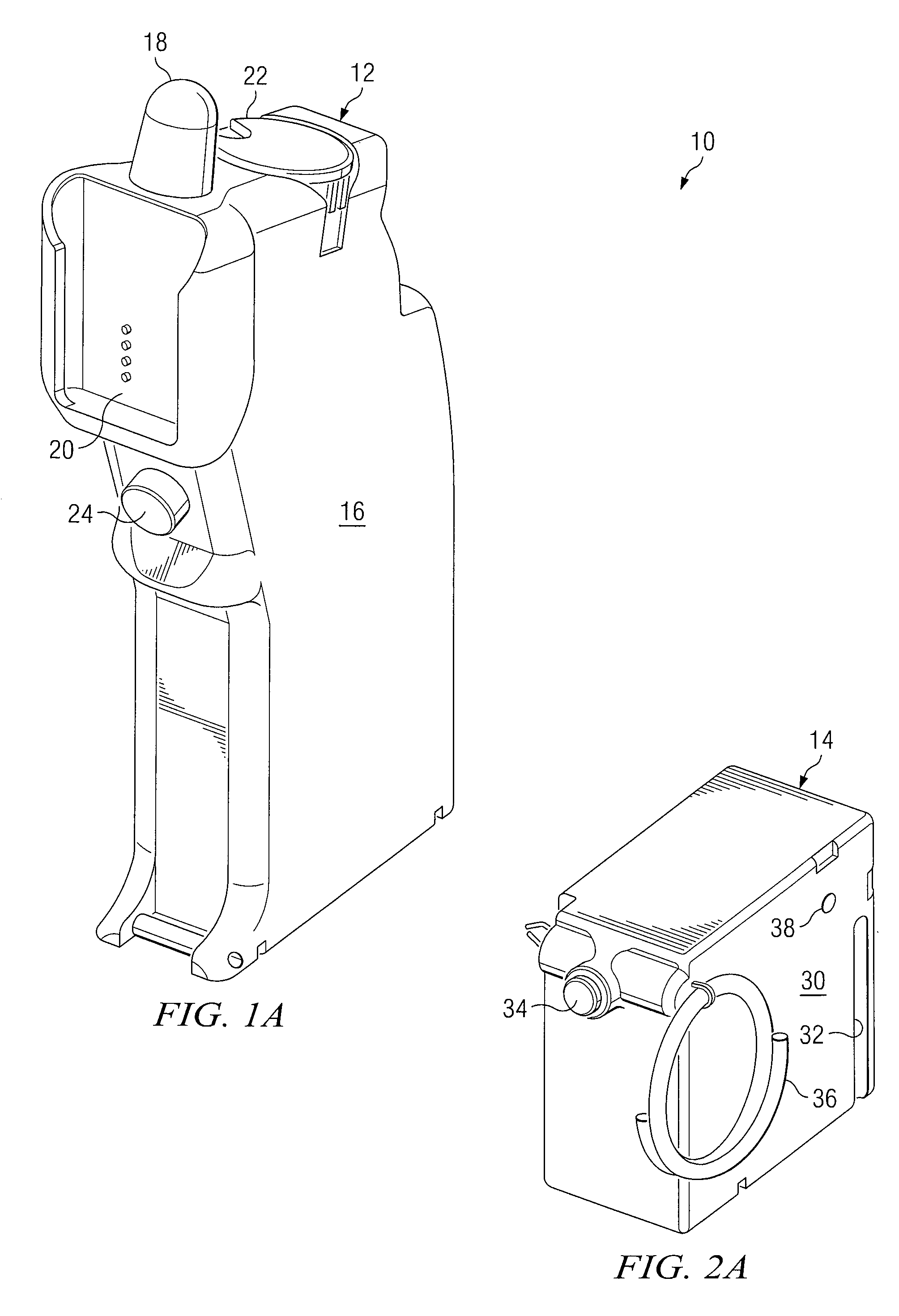
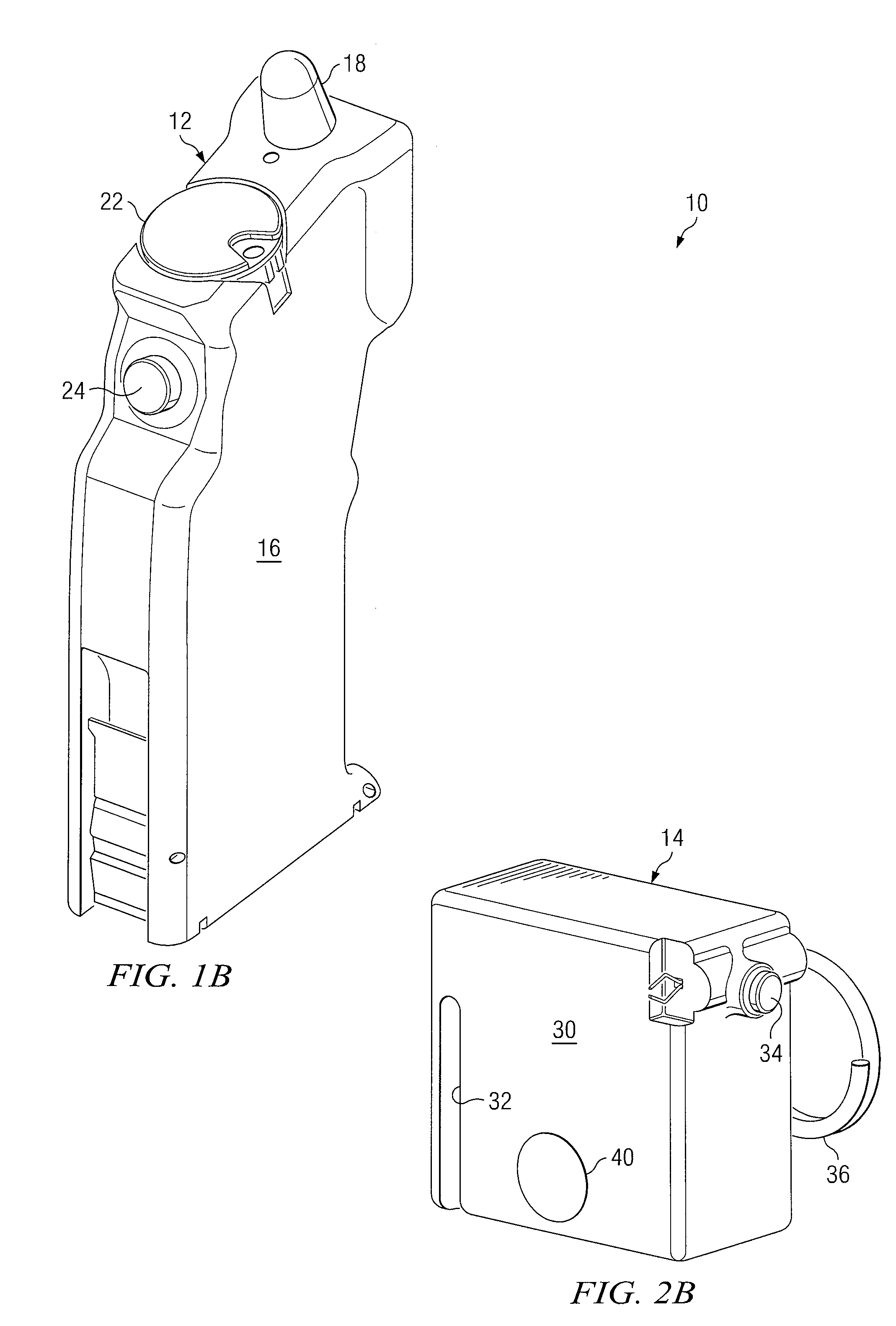
[0016]FIGS. 1A through 2B show one embodiment of a remote explosive detonation system 10. Remote explosive detonation system 10 generally includes a transmitter 12 and at least one receiver 14. The transmitter 12 transmits an electro-magnetic signal that may be received by receiver 14 to detonate an explosive (not shown). As will be described in detail below, the transmitted electro-magnetic signal may include an identification code that may be used by the receiver 14 to ensure validity of the transmitted signal. Thus in some embodiments, remote explosive detonation system 10 may provide relatively secure remote explosive detonation of explosives without creating a resi...


PUM


Abstract

According to one embodiment of the disclosure, a remote explosive detonation system includes a transmitter and at least one receiver having a detonator. The transmitter transmits an electro-magnetic signal having a transmitter identification code that may be received by the receiver. The receiver initiates the detonator if the transmitter identification code matches an internal identification code stored in the receiver.

Description

RELATED APPLICATIONS[0001]This application claims priority to U.S. Provisional Patent Application Ser. No. 61 / 002,476, entitled “REMOTE DETONATION SYSTEM,” which was filed on Nov. 9, 2007.TECHNICAL FIELD OF THE DISCLOSURE[0002]This disclosure generally relates to explosives, and more particularly, to a remote explosive detonation system for explosives and a method of operating the same.BACKGROUND OF THE DISCLOSURE[0003]Explosives used in military combat may be initiated by detonation devices. Due to the destructive nature of explosives, these detonation devices may incorporate various safety features to avoid premature detonation. For example, a shock tube is a type of detonation device that transmits a detonation signal to a remotely located explosive using a pressure signal. The shock tube may be made of non-conductive materials, which are not generally susceptible to premature detonation caused by stray electro-magnetic radiation.SUMMARY OF THE DISCLOSURE[0004]According to one em...

Claims


Application Information

Patent Timeline
IPC IPC(8): F42B3/10F42D1/045F42D1/05F42C11/00F42C21/00
CPCF42C17/04F42D1/05F42D1/043
Inventor PLUMMER, BRADY A.FISHER, DELMER D.KNOPF, IAN A.PLUMMER, ROBERT W.GALANTI, BENJAMIN J.LEWIS, JR., JOE L.HENSLEY, MARION P.
Owner RAYTHEON CO
Why Eureka
Try Eureka