Mandrel for forming an aggregate pier, and aggregate pier compacting system and method

Inactive Publication Date: 2017-03-02
NIROUMAND BAHMAN
View PDF13 Cites 22 Cited by
  • Summary
  • Abstract
  • Description
  • Claims
  • Application Information

AI Technical Summary

Benefits of technology

[0013]The invention disclosed herein addresses the above-mentioned need for a method of construction of aggregate piers, which is environment friendly, applicable to loose soils, and applicable in regions having water shortages. Furthermore, the invention disclosed herein addresses the need for an aggregate compacting system, which occupies minimum space and is easy to handle. Moreover, the invention disclosed herein addresses the need for a system and method of compacting aggregate piers, which are deployable in regions having high water table. Furthermore, the invention addresses the need for a method, which is applicable in loose soils with high water lev

Problems solved by technology

Recently, with the growth of urban and industrial areas, and the shortage of land and high quality materials, demand for use of marginal lands is increasing.
Furthermore, loose granular soils have the great potential of liquefaction.
Aggregate piers with depths of more than 10 meters are not as economical as deep concrete foundations.
The wet process produces a great deal of environmental pollution especially in limited area of urban lands due to exit slurry from the wells and the need for surrounding areas for construction of sediment basins.
Furthermore, the wet process cannot be applied to loose soils and soils with low bearing strength.
In such soils, the probability of destruction of buildings surrounding the excavated area is higher.
In areas having water shortages, it is disadvantageous to use water that is mandatory for the wet process.
Moreover, heavy machinery and equipment are needed for the vibro-replacement wet method.
The great height and volume of heavy machinery and inabil

Method used


Image

  • Mandrel for forming an aggregate pier, and aggregate pier compacting system and method
  • Mandrel for forming an aggregate pier, and aggregate pier compacting system and method
  • Mandrel for forming an aggregate pier, and aggregate pier compacting system and method

Examples


Example

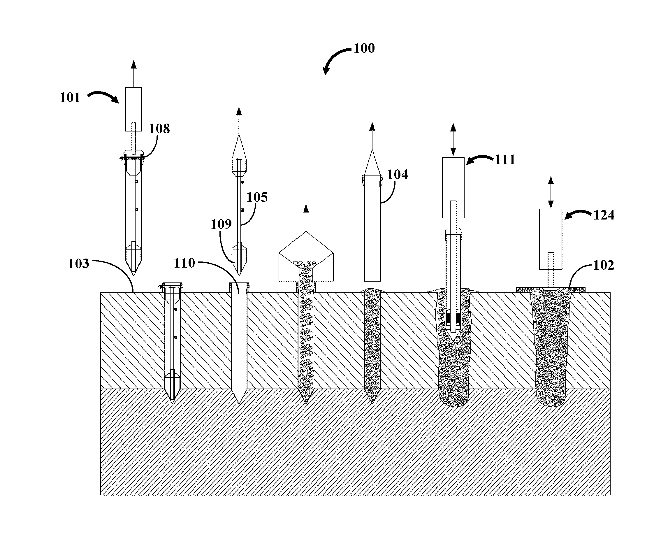
[0051]The present invention generally relates to ground improvement. More particularly, the invention disclosed herein relates to methods and an aggregate pier compaction system for ground improvement by forming compact aggregate piers using aggregates, for example, gravel.

[0052]A description of embodiments of the present invention will now be given with reference to the Figures. It is expected that the present invention may be embodied in other specific forms without departing from its spirit or essential characteristics. The described embodiments are to be considered in all respects only as illustrative and not restrictive. The scope of the invention is, therefore, indicated by the appended claims rather than by the foregoing description. All changes that come within the meaning and range of equivalency of the claims are to be embraced within their scope.

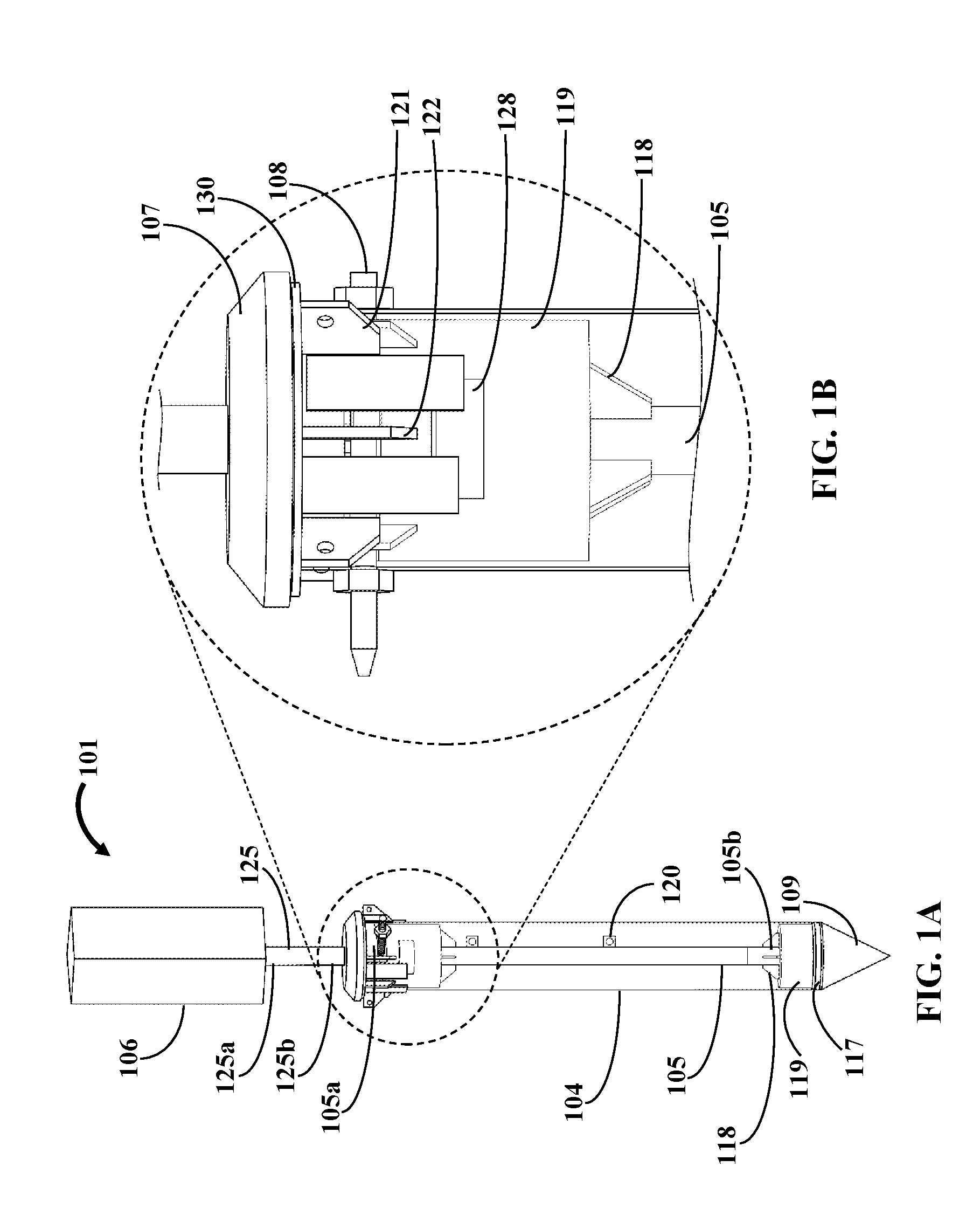
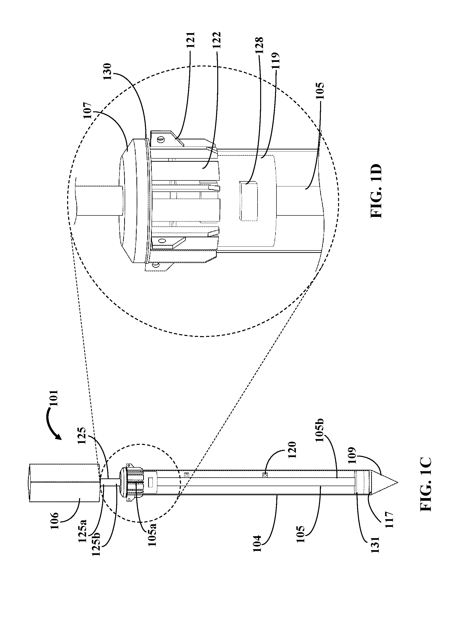
[0053]FIGS. 1A-1B exemplarily illustrates perspective views of different embodiments of a mandrel 101. The mandrel 101 for formi...


PUM


Abstract

An aggregate pier compacting system for forming a compacted aggregate pier (AP) at a target location includes a mandrel, a tamper device, and a finishing tamper device. The mandrel includes a casing for housing a drilling shaft (DS). An external vibratory hammer (EVH) repeatedly impacts a hammer element (HE) extending from the DS. The DS transfers the impact to a bore head to form a cavity at the target location. The DS is removed and the casing is filled with aggregate. The tamper device includes a compacting shaft. The EVH impacts a second HE extending from the compacting shaft and transfers the impact to a compaction head to form the compacted AP. The finishing tamper device includes a shaft. The EVH impacts a third HE extending from the shaft and transfers the impact to a finishing head compacting a top layer of the AP to form a finished AP.

Description

BACKGROUND OF THE INVENTION[0001]Recently, with the growth of urban and industrial areas, and the shortage of land and high quality materials, demand for use of marginal lands is increasing. Additionally, techniques and equipment for improvement of loose and soft soil have been proposed. Generally, soft cohesive soils have two main characteristics, the first one is the low shear strength, and the second one is large settlement. Furthermore, loose granular soils have the great potential of liquefaction.[0002]In the last few decades, compaction using sandy or gravelly columns, pile, piers, etc., has been conducted all over the world as a technical and an economical method. In practice, various methods of compacting gravelly piers were founded on one of the construction replacement, construction displacement, or combination methods. However, the final products, construction process, the configuration, and the effect on the relative density of gravel and matrix soil, which were construc...

Claims


Application Information

Patent Timeline
IPC IPC(8): E02D3/08E02D5/60E02D27/18E02D27/26E02D5/62E02D27/14
CPCE02D3/08E02D5/62E02D5/60E02D27/18E02D27/26E02D27/14E02D3/02
Inventor NIROUMAND, BAHMAN
Owner NIROUMAND BAHMAN
Why Eureka
Try Eureka