Hinged Attachment of Headgear to a Helmet

Active Publication Date: 2011-12-29
GENTEX CORP
View PDF8 Cites 69 Cited by
  • Summary
  • Abstract
  • Description
  • Claims
  • Application Information

AI Technical Summary

Benefits of technology

[0018]In a third aspect, the invention relates to a safety helmet comprising a bulge or protrusion on a side thereof to form a cavity therein, the cavity extending to a terminal edge of the helmet and overlying a wearer's ear, a fixture attached to the helmet above the bulge

Problems solved by technology

Unfortunately, because the earphones add weight and do not function in dismounted operations, and cannot be removed, the vehicle crew members are issued two helmets—the CVC helmet and a standard infantry helmet.
In some cas

Method used


Image

  • Hinged Attachment of Headgear to a Helmet
  • Hinged Attachment of Headgear to a Helmet
  • Hinged Attachment of Headgear to a Helmet

Examples


Embodiment Construction

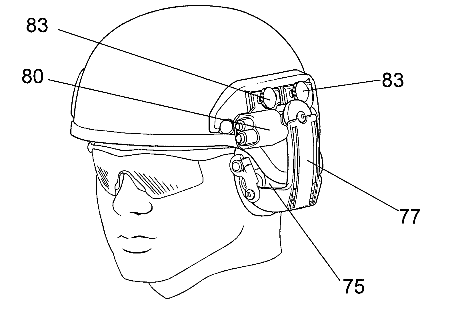
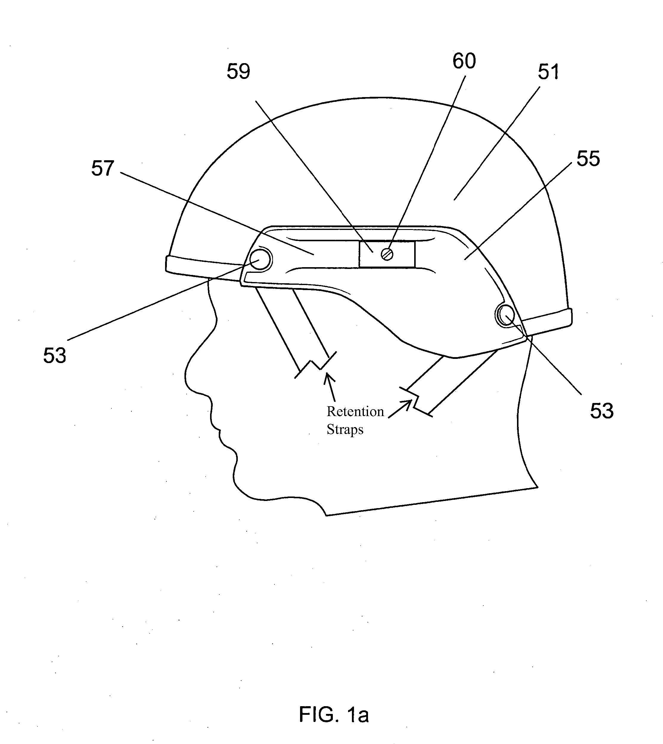
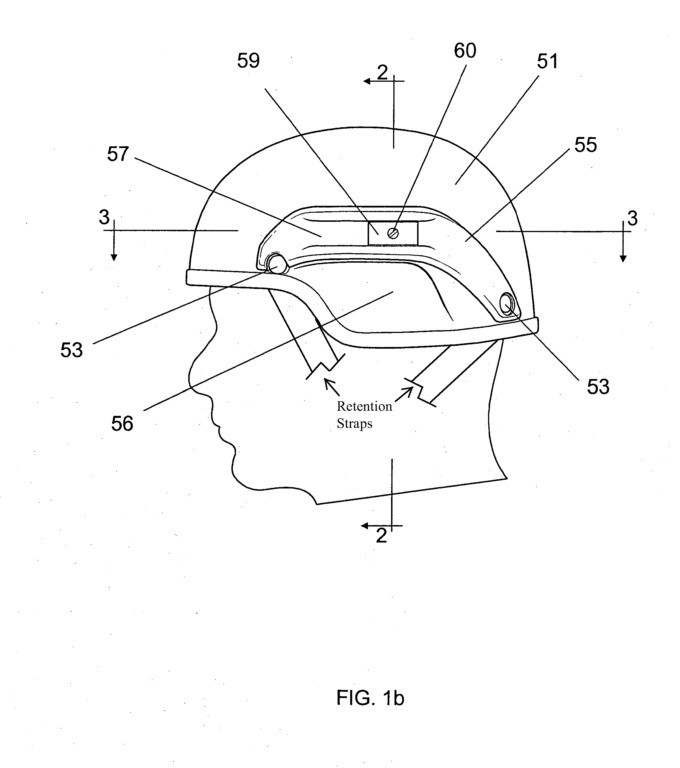
[0042]For ease of presentation, the present discussion focuses first on a suitable mounting rail to which a hinged ear-accessory retention system may be mounted; preferred embodiments of the ear-accessory retention system itself are then described.

[0043]Mounting Rail

[0044]With reference to FIG. 1a, a helmet shell 51 is shown from the left side of the user's head (the right side having symmetrical features). A mounting rail 55 is included within a fixture preferably fabricated from nylon, polypropylene, or other synthetic plastic using injection molding processes, the bottom edge of which conforms to the bottom edge of the helmet shell 51. The fixture is secured to the exterior of helmet shell 51 by means of fasteners 53 in the front and back. In another embodiment, illustrated in FIG. 1b, mounting rail 55 is included within a fixture having a bottom edge that conforms to a convex extension 56 of helmet shell 51.

[0045]A recessed groove 57 in the mounting rail 55 slidably accepts a co...


PUM


Abstract

A hinge mechanism for attaching ear accessories to a helmet allows an accessory to be attached at a point outside the helmet shell utilizing, for example, a slidable mounting rail, and to reach under the edge of the helmet shell so that the accessory is supported in contact with the wearer's head. The hinge mechanism is well suited for use in connection with military helmets that have a “bulge” or protrusion over the ear.

Description

RELATED APPLICATIONS[0001]The present application is a continuation-in-part of U.S. Ser. No. 11 / 350,591, filed on Feb. 9, 2006, which claims priority to, and the benefits of, U.S. Ser. No. 60 / 691,307, filed Jun. 17, 2005; the present application also claims priority to U.S. Ser. No. 60 / 811,896, filed on Jun. 8, 2006. The entire disclosures of these applications are hereby incorporated by reference.FIELD OF THE INVENTION[0002]This invention relates to safety helmets, and in particular to attachment of accessories that may be optionally mounted onto the helmet.BACKGROUND OF THE INVENTION[0003]Helmets for head protection are worn in a variety of environments and for various purposes. Accessories may be added to the helmet according to the needs of the wearer and the demands of the use environment. Such accessories may, for example, provide additional protection, as in the case of a face shield; additional capability such as night vision; or communication in the case of earpieces.[0004]...

Claims


Application Information

Patent Timeline
IPC IPC(8): A42B3/04A42B3/08
CPCA42B3/04G02B23/12A42B3/0406
Inventor ROGERS, DAVID C.ROGERS, CHARLES H.KEITH-LUCAS, DARWIN
Owner GENTEX CORP
Why Eureka
Try Eureka