Catheter sheath for implant delivery

a catheter and catheter technology, applied in the field of material tubes, can solve problems such as breaking or being at risk of breaking under such applied forces, and achieve the effects of low curvature deflection, high curvature deflection, and large radius

Active Publication Date: 2012-01-26
CR BARD INC
View PDF13 Cites 379 Cited by
  • Summary
  • Abstract
  • Description
  • Claims
  • Application Information

AI Technical Summary

Benefits of technology

[0010]According to a first aspect of the present invention, there is provided a tube of material having a seam extending between a proximal end and a distal end, two edges of the material meeting and at least partially overlapping along the seam and being sewn together at the seam by stitches of relatively flexible thread, the thread of one or more of the stitches passing from a first side of the overlapped edges of material, through both layers of overlapped material, crossing a relatively rigid member which is disposed on a second, opposite side of the overlapped edges of material, and passing back to the first side. The relatively rigid member can resist unwanted small radius, high curvature deflection lateral to the seam, although is flexible with larger radius, low curvature deflections of the tube. The relatively rigid member is thus able to be removed from between the stitches which cross it and the second side of the overlapped tube material with certainty and precision, and without risk of breaking as it is manipulated for removal. The relatively flexible thread is able to adopt the small radius, high curvature needed to form a stitch, but need only be strong enough in tension to resist the seam pulling apart in normal use. The relatively flexible thread need not be strong enough to allow the one or more stitches to be pulled out from one end of the tube, and may break or be at risk of breaking under such applied forces, especially if the thread is long or there are multiple stitches. The different characteristics of the relatively flexible thread and relatively rigid member are thus used to render each one suitable for its own purpose in forming a stitched seam that can be reliably released. Because each component is selected to have properties suited to its specific role, dimensions of the components can be reduced and overall size of the seam structure substantially minimised.

Problems solved by technology

The relatively flexible thread need not be strong enough to allow the one or more stitches to be pulled out from one end of the tube, and may break or be at risk of breaking under such applied forces, especially if the thread is long or there are multiple stitches.

Method used


Image

  • Catheter sheath for implant delivery
  • Catheter sheath for implant delivery
  • Catheter sheath for implant delivery

Examples


Embodiment Construction

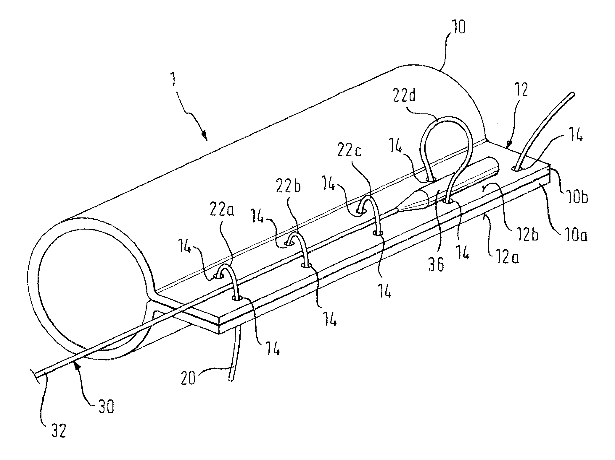
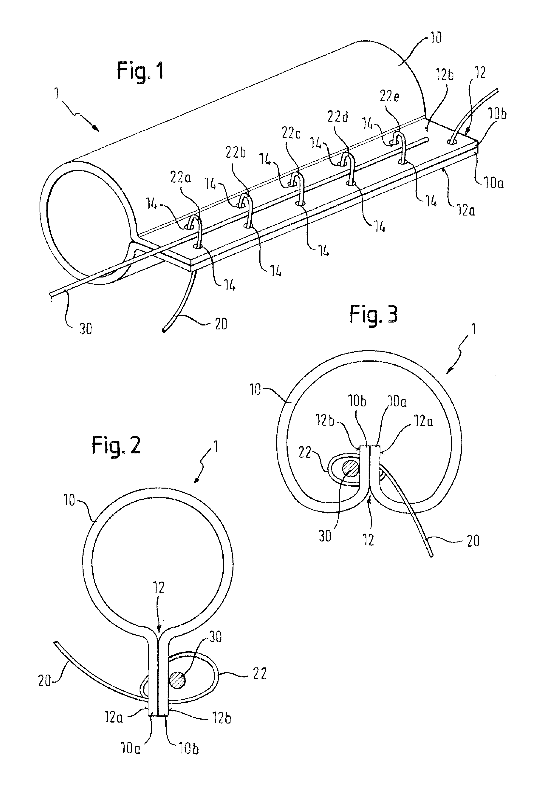
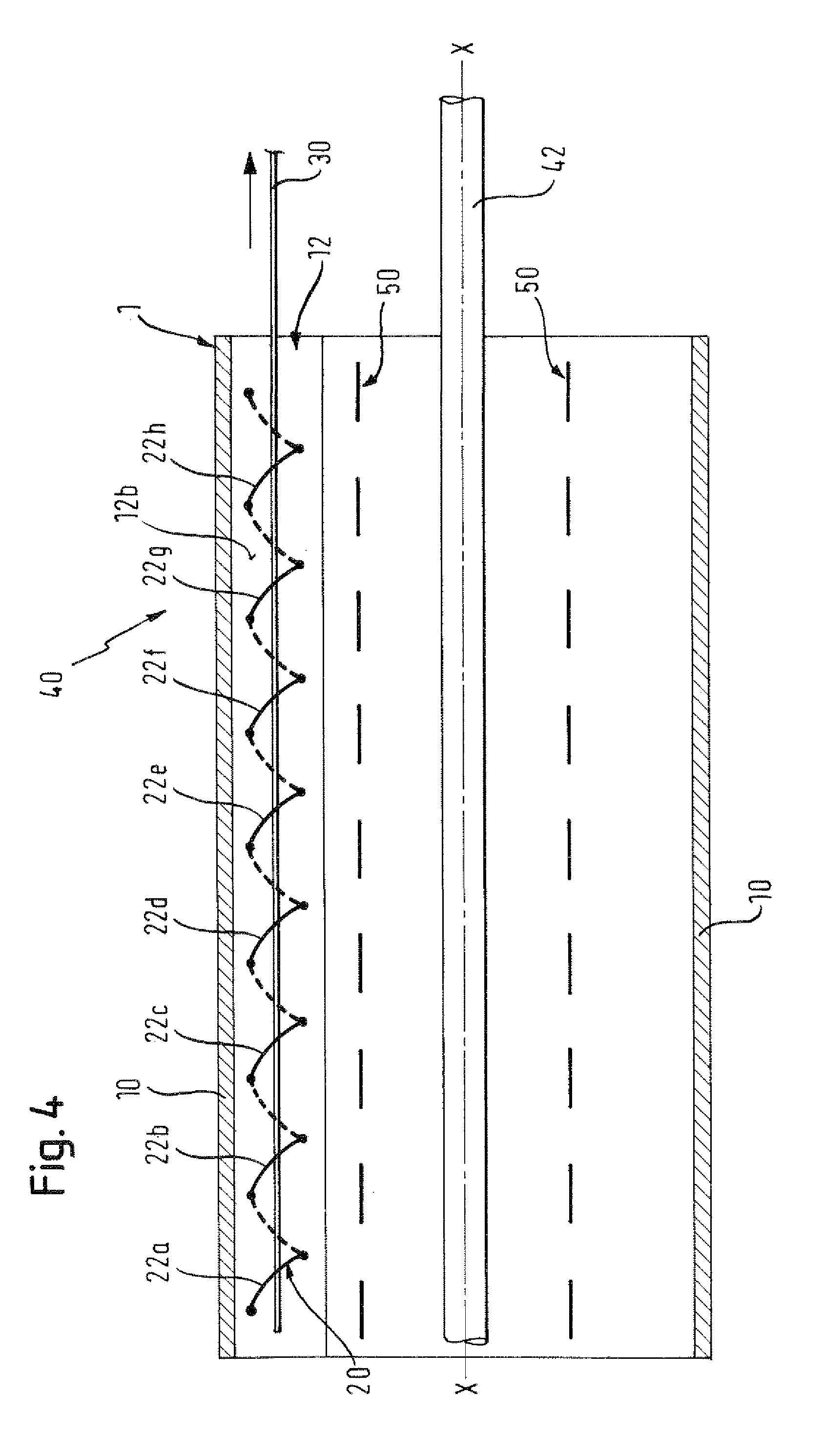
[0056]Specific embodiments of the present invention will now be described, with reference to the illustrated examples shown in the accompanying drawings. Reference to the drawings is made for illustrative purposes, and should not to be taken to be limiting of the scope of the claims.

[0057]In general, embodiments of a tube of material are formed by folding a sheet of the material so as to bring two edges of the material together to form a seam. Alternatively, a larger-diameter tube of the material may be pressed together to bring two portions of its internal surface together along its length, thereby forming a smaller-diameter tube with edges in a seam. The material from which the tube is made can be any suitable biocompatible material, as is well known to the person skilled in the art for such applications, including ePTFE, polyethers such as polyterephthalate (DACRON® or MYLAR®), or polyaramids such as KEVLAR®. Any other suitable polymer, fabric or a foil of metallic material may b...


PUM


Abstract

There is disclosed herein a tube of material (1) having a seam (12) extending between a proximal end and a distal end, two edges (10a, 10b) of the material meeting and at least partially overlapping along the seam (12) and being sewn together at the seam by stitches (21, 22, 24) of relatively flexible thread (20), the thread of one or more of the stitches (22, 24) passing from a first side (12a) of the overlapped edges (10a, 10b) of material, through both layers of overlapped material, crossing a relatively rigid member (30) which is disposed on a second, opposite side (12b) of the overlapped edges of material, and passing back to the first side (12a). There is further disclosed an implant delivery catheter (40) incorporating the tube of material (1), and associated methods for its manufacture.

Description

FIELD OF THE INVENTION[0001]The present invention relates to a tube of material, to associated methods of manufacturing a tube of material, and to an implant delivery catheter incorporating such a tube of material. The tube of material may be of a form that can be used as a releasable outer sheath for delivering expandable or self-expanding implants, such as stents.BACKGROUND[0002]Numerous implant delivery systems have been devised for conveying and deploying prosthetic implants in the human body. Continued development in the field of material science has enabled an increasingly diverse range of implants to be devised which can be delivered to and implanted non-invasively at a treatment location. Such implants will typically have a low-profile delivery configuration and are expanded to a large-profile operative configuration at the treatment location. These implants can either be expanded mechanically to their operative configuration, for example by the use of balloons or pull-wires...

Claims


Application Information

Patent Timeline
Patent Type & Authority Applications(United States)
IPC IPC(8): A61F2/84D05B1/02A61F2/95A61F2/97
CPCA61F2/95A61F2002/9511A61F2/97A61F2/962
Inventor WUBBELING, MARTIN
Owner CR BARD INC
Why Eureka
Try Eureka