Clamping ring for fastening a gas generating cartridge

a gas generator and clamping ring technology, which is applied in the direction of hose connection, pedestrian/occupant safety arrangement, vehicular safety arrangement, etc., can solve the problems of reducing the elasticity, which is essential for safe holding the gas generator cartridge, and the cost of the screw clamping

Inactive Publication Date: 2009-12-15
HANS OETIKER MASCHEN & APPFAB
View PDF29 Cites 12 Cited by
  • Summary
  • Abstract
  • Description
  • Claims
  • Application Information

AI Technical Summary

Benefits of technology

[0005]It is an object of the invention to avoid at least part of the disadvantages which occur with comparable clamping rings of the prior art. A more specific object resides in the provision of a clamping ring, particularly for mounting gas generator cartridges, which ensures a high torque and which is as easy to fix as possible.
[0006]This object is met by a clamping ring further including a wave formed in the ring for increasing the holding force between the ring and the object, the wave having two convex arches projecting outward from the ring and an inward convex arch therebetween, the apex of the inward arch being situated substantially on a circle defined by the remaining portions of the ring. The configuration of the clamping ring profile results in a surprisingly high holding force, which may be caused by the elastic cooperation between the tensioning ear and the wave and also by the pressure by which the inward convex arch existing between the two outward arches of the wave engage the object to be mounted, i.e., the gas generator cartridge. The tests referred to above have shown that the clamping ring according to the invention withstands torques of up to 13 Nm with a direct metal / metal engagement. At the same time, the clamping ring, which is tensioned by merely narrowing the ear, has the advantage of being easy to mount.
[0007]The inward arch having a larger radius than the outward arches is of advantage for achieving a suitable elasticity and a defined pressure between the inward arch and the cartridge. The wave being positioned diametrically opposite the tensioning ear is beneficial because of the elastic interaction between the integrated wave and the tensioning ear.
[0008]The forming the clamping ring from tubular material results in a clamping ring which is stable in shape and easy to manufacture.
[0011]The integration of part of the support plate carrying the gas generator cartridge into the clamping ring is of advantage concerning the holding force and safety of the mounting.

Problems solved by technology

Screw clamps, however, are expensive in manufacture and, moreover, time consuming in assembly, specifically because care must be taken that the screws are fastened with a predetermined torque to ensure the required holding force.
Moreover, it has been found with screw clamps that the elasticity, which is essential for safely holding the gas generator cartridge, decreases with time.

Method used


Image

  • Clamping ring for fastening a gas generating cartridge
  • Clamping ring for fastening a gas generating cartridge

Examples


Embodiment Construction

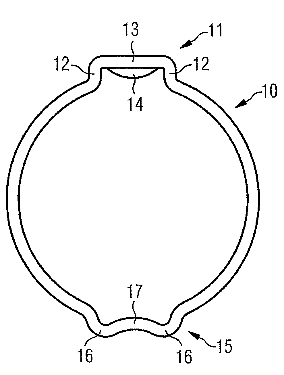
[0016]The closed clamping ring 10 shown in FIG. 1 consists of a tube section made of zinc galvanised steel which has a width of 10 mm in the axial direction, a wall thickness of 1.5 mm, and an inner diameter of 28.5 mm in the non-tensioned condition shown.

[0017]For tensioning the clamping ring 10 about an object to be mounted (not shown in FIG. 1), the clamping ring has a so-called “Oetiker ear”11 which includes two outward extending legs 12 interconnected by a web 13. A reinforcing bead 14 is stamped into the web 13. In the embodiment shown, the inner distance between the legs, which are parallel in the non-tensioned condition, is 8 mm. The ear 11 is tensioned by being narrowed to a predetermined degree by means of a pliers-type special tool with jaws which engage the legs 12 near their inner ends.

[0018]A wave generally identified by 15 is formed in the clamping ring 10 diametrically opposite the ear 11. The wave 15 includes two outward arches 16 which extend outward from the ring ...


PUM

PropertyMeasurementUnit
thicknessaaaaaaaaaa
axial widthaaaaaaaaaa
wall thicknessaaaaaaaaaa

Abstract

A clamping ring is used to mount an air bag gas generator cartridge on a support plate. A tensioning ear is formed in the clamping ring. Further, a wave is formed in the ring to increase the holding force between the ring and the cartridge. The wave consists of two convex arches projecting outward from the ring and an inward convex arch therebetween, the apex of the inward arch being at least tangential to the circle defined by the remaining portions of the ring in the initial condition of the ring. This type of clamping ring mounting is capable of withstanding torques between the cartridge and the support plate of well above 10 Nm.

Description

PRIOR ART[0001]Gas generator cartridges for vehicle airbags, specifically airbags for restraining the head, are often mounted on a support plate by means of two clamping rings, the support plate being mounted on the vehicle body. In view of the substantial forces which occur when the cartridge is triggered, it is required that the mounting of the cartridge on the support plate withstands a torque of at least 10 Nm.[0002]This requirement can be met by means of screw clamps. Screw clamps, however, are expensive in manufacture and, moreover, time consuming in assembly, specifically because care must be taken that the screws are fastened with a predetermined torque to ensure the required holding force. Moreover, it has been found with screw clamps that the elasticity, which is essential for safely holding the gas generator cartridge, decreases with time.[0003]Tests made with stepless ear clamps such as known from U.S. Pat. No. 5,305,499 have shown that a torque of up to only 3.5 Nm is a...

Claims


Application Information

Patent Timeline
Patent Type & Authority Patents(United States)
IPC IPC(8): F16L25/00B65D45/00B60R21/213
CPCB60R21/2171F16B2/005B60R21/213Y10T24/1457Y10T24/1478Y10T292/28Y10T292/20Y10T292/205
Inventor MEIER, ULRICHBERLEP, THOMAS
Owner HANS OETIKER MASCHEN & APPFAB
Why Eureka
Try Eureka