Projector

a projector and projection image technology, applied in the field of projectors, can solve the problems the increase of color shading in the projection image, and achieve the effects of preventing overheating of the phosphor layer, preventing degradation of emission efficiency, and superior reliability

Inactive Publication Date: 2012-03-01
SEIKO EPSON CORP
View PDF29 Cites 10 Cited by
  • Summary
  • Abstract
  • Description
  • Claims
  • Application Information

AI Technical Summary

Benefits of technology

[0019]According to this configuration, since the overheating of the phosphor layer can be prevented by rotating the plate member having the phosphor layer formed on one surface thereof while irradiating t

Problems solved by technology

However, there arises a problem that the shift in the illumination due to the temporal change such as the displacement of the light emitting point of the light source is different between the colors.
As a result, there arises the problem that the color shading in the projection image increases.
In other words, in the case of assigning

Method used


Image

  • Projector
  • Projector
  • Projector

Examples


first embodiment

[0028]Hereinafter, a first embodiment of the invention will be explained with reference to FIGS. 1 through 3, 4A, and 4B.

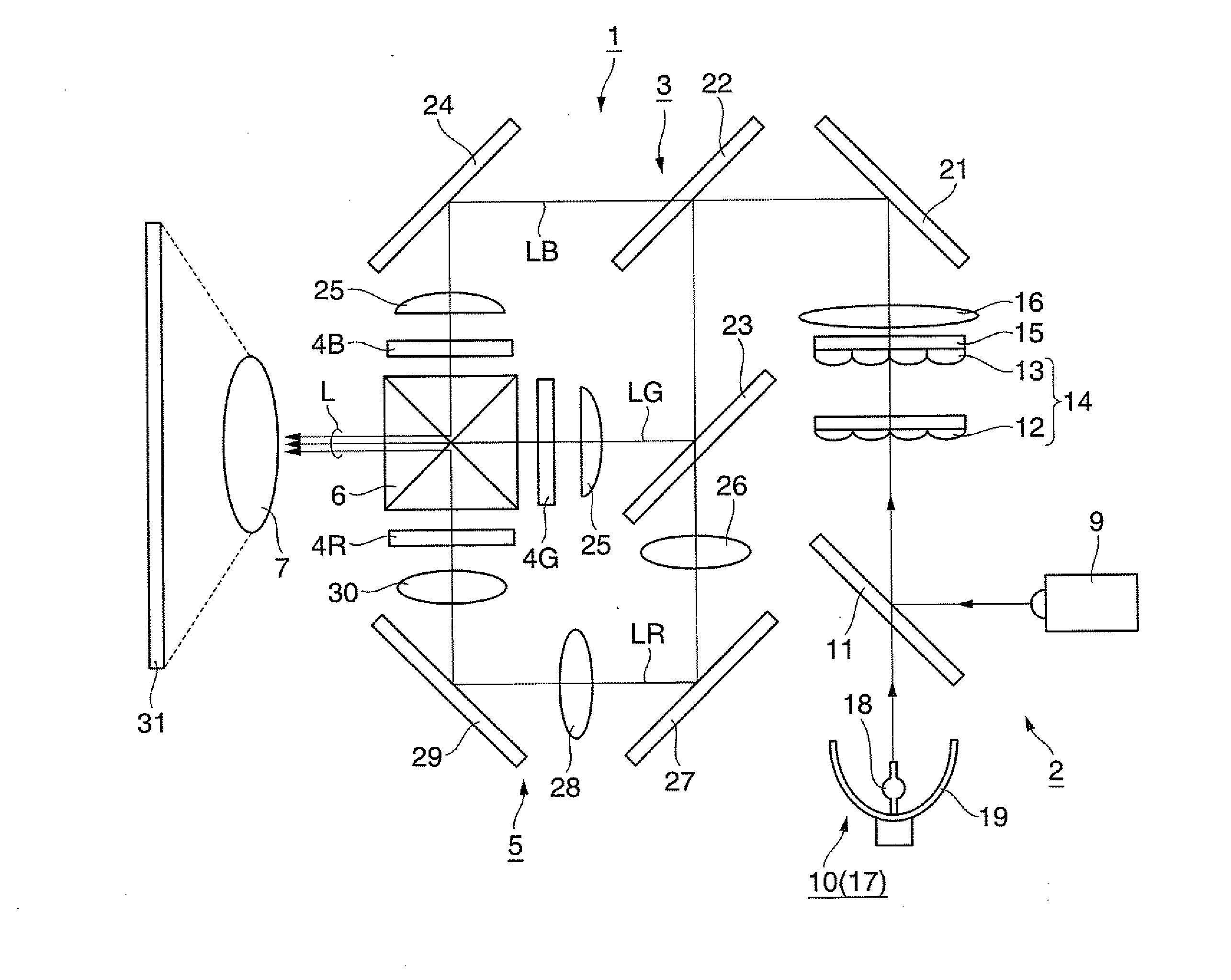
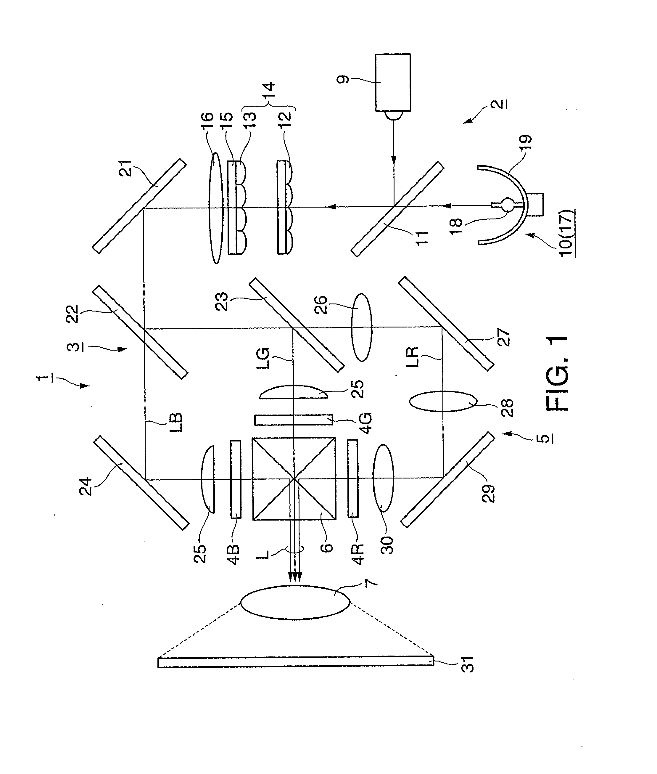
[0029]The projector according to the present embodiment is a projector provided with liquid crystal light valves respectively modulating the three colors of colored lights, red (R) light, green (G) light, and blue (B) light, namely a so-called three-panel liquid crystal projector. Further, in the present embodiment, a configuration of inserting a relay optical system in the light path of the red light out of the three colors of colored lights will be explained as an example.

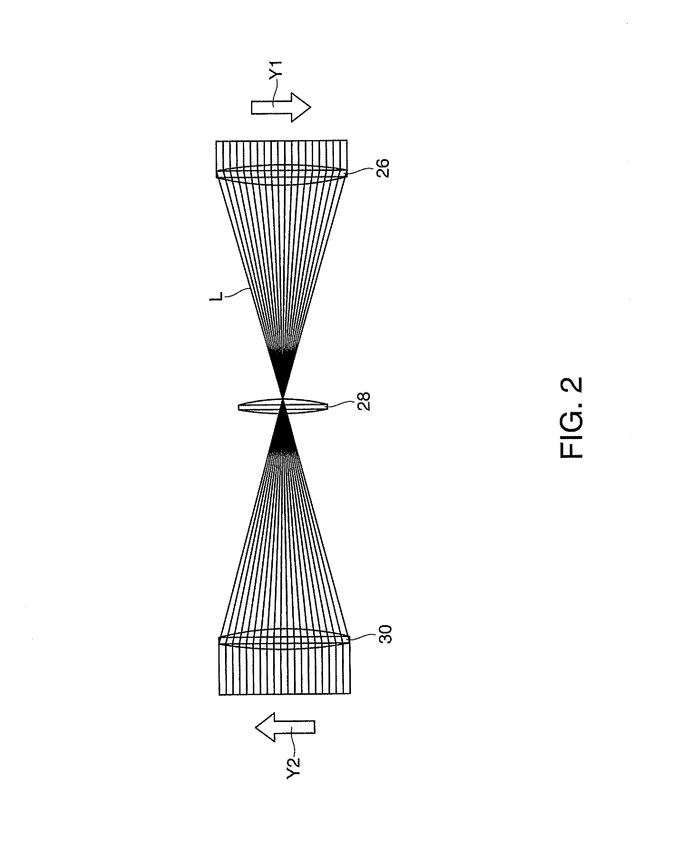
[0030]FIG. 1 is a schematic configuration diagram of the projector according to the present embodiment. FIG. 2 is a diagram for explaining the operation of the relay optical system. FIG. 3 is a diagram for explaining the operation of an optical system except the relay optical system. FIGS. 4A and 4B are diagrams for explaining an operation and an advantage of the projector.

[0031]It should be no...

second embodiment

[0050]Hereinafter, a second embodiment of the invention will be explained with reference to FIG. 5.

[0051]The basic configuration of the projector according to the present embodiment is substantially the same as that of the first embodiment, and is different from that of the first embodiment in the configuration of the illumination section and in the point that the relay optical system is inserted in the light path of the blue light.

[0052]FIG. 5 is a schematic configuration diagram of the projector according to the present embodiment. In FIG. 5, the constituents common to FIG. 1 used in the first embodiment are denoted with the same reference symbols, and the explanation therefor will be omitted.

[0053]As shown in FIG. 5, the projector 41 according to the present embodiment is mainly composed of an illumination section 42, a color separation section 43, the liquid crystal light valves 4R, 4G, and 4B (the light modulation elements), the relay optical system 5 (the light transmission se...

third embodiment

[0058]Hereinafter, a third embodiment of the invention will be explained with reference to FIG. 6.

[0059]The basic configuration of the projector according to the present embodiment is substantially the same as that of the first embodiment, but is different from that of the first embodiment in the configuration of the illumination section. Further, it is substantially the same as that of the second embodiment in the point that the relay optical system is inserted in the light path of the blue light.

[0060]FIG. 6 is a schematic configuration diagram of the projector according to the present embodiment. In FIG. 6, the constituents common to FIG. 1 used in the first embodiment are denoted with the same reference symbols, and the explanation therefor will be omitted.

[0061]As shown in FIG. 6, the projector 61 according to the present embodiment is mainly composed of an illumination section 62, the color separation section 43, the liquid crystal light valves 4R, 4G, and 4B (the light modula...


PUM


Abstract

A projector according to an embodiment of the invention includes a first light source adapted to emit a light including a first colored light, a second light source adapted to emit a light including a second colored light and a third colored light, a color separation section to which the lights emitted from the respective light sources are input, and adapted to separate the incident lights into a first colored light, a second colored light, and a third colored light, liquid crystal light valves (first through third light modulation elements), and a relay optical system (a light transmission section) including a plurality of optical elements disposed between the color separation section and the first light modulation element.

Description

BACKGROUND[0001]1. Technical Field[0002]The present invention relates to a projector.[0003]2. Related Art[0004]A projector provided with a color separation optical system for separating light from a light source into three colors of colored lights, a display optical system having three light modulation devices corresponding respectively to the colored lights, and color combining optical system for combining the lights modulated by the respective light modulation devices is disclosed in the specification of U.S. Pat. No. 4,943,154. In this projector, it is arranged that the reduction of the light intensity and the initial color variation are prevented by setting the light path lengths (the distances from the light source to the light modulation devices) of the three colors of colored lights in the color separation optical system equivalent to each other. Specifically, in this projector, the light path lengths of the respective colored lights are made optically equivalent by making a ...

Claims


Application Information

Patent Timeline
IPC IPC(8): G03B21/14
CPCG03B21/2013H04N9/317G03B33/12G03B21/2053
Inventor YANAI, HIROAKI
Owner SEIKO EPSON CORP
Why Eureka
Try Eureka