Vibration suppressing device

Inactive Publication Date: 2012-03-15
OKUMA CORP
View PDF7 Cites 15 Cited by
  • Summary
  • Abstract
  • Description
  • Claims
  • Application Information

AI Technical Summary

Benefits of technology

[0014]According to the aspects of the present invention, the machining operation is started at a rotation speed with lower possibility of generating the “chatter vibration” than in the case rotated at the command rotation speed. Therefore, it becomes likely to perform machining operation never generating the “chatter vibration”. Accordingly, it is possible to finish a highly accurate machined surface without any chattering mark remained, and machining efficiency and machined surface accuracy can be improved.
[0015]According to the second aspect of the present invention, generation of the “chatter vibration” is detected even during machining operation at a stable rotation speed. When the “chatter vibration” has been detected, a new stable rotation speed is calculated, and the machining operation is continued at the new stable rotation speed. The new stable

Problems solved by technology

Conventionally, in a machine tool rotating a tool to grind the surface of a workpiece for example, chatter vibration may possibly be generated during the machining operation due to low rigidity of the tool and the like.
Further, machining efficiency deteriorates, and machined surface accuracy becomes inferior, and the like.
However, when the machining operation is st

Method used


Image

  • Vibration suppressing device
  • Vibration suppressing device
  • Vibration suppressing device

Examples


Example

Embodiment 1

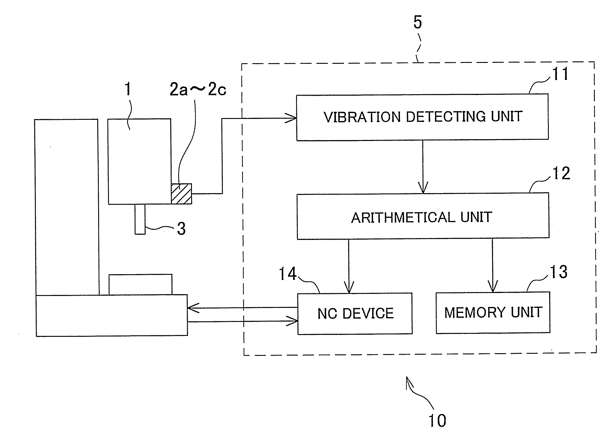
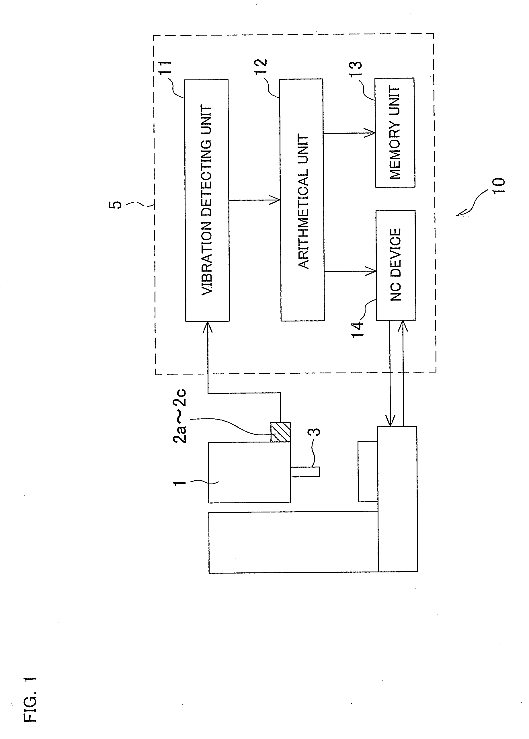
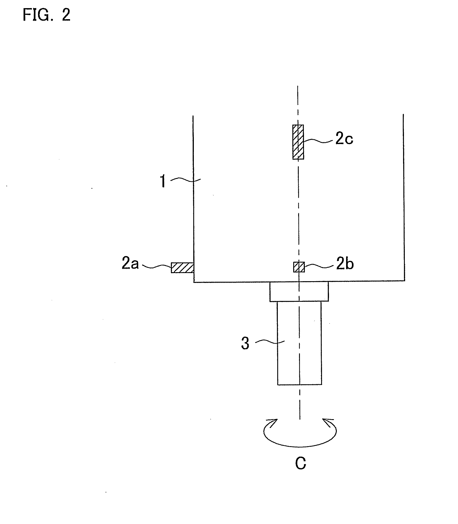
[0033]FIG. 1 is an explanatory drawing showing a block constitution of a vibration suppressing device 10. FIG. 2 is an explanatory drawing showing a side view of a rotary shaft housing 1 that is an object of suppressing vibration, and FIG. 3 is an explanatory drawing showing an axial view of the rotary shaft housing 1.

[0034]The vibration suppressing device 10 is a device for suppressing “chatter vibration” generated in a rotary shaft 3 provided rotatably around C-axis in the rotary shaft housing 1, and includes vibration sensors 2a-2c for detecting time-domain vibrational acceleration (that means vibrational acceleration on a time axis) that is a characteristic value accompanying vibration generated in the rotary shaft 3 during rotation, and a control device 5 analyzing values detected by the vibration sensors 2a-2c to determine whether the “chatter vibration” has been generated or not and controlling the rotation speed of the rotary shaft 3 based on the result of the de...

Example

Embodiment 2

[0053]Next, another embodiment of the present invention will be described based on the drawings.

[0054]FIG. 7 is a schematic configuration diagram showing a vertical machining center that is an example of a machine tool and a vibration suppressing device 100 arranged in the vertical machining center.

[0055]First, the vertical machining center 21 has a known constitution that a main spindle 23 as a rotary shaft rotatable around the C-axis is provided in a main spindle head 22 arranged in the upper part, and a workpiece 26 set on a working table 25 below is machined by a tool 24 attached to the main spindle 23. In the machining center 21, an NC device 112 controls rotation of the main spindle 23 according to an NC program, and the tool 24 is automatically changeable by an automatic tool changing device (not shown).

[0056]The vibration suppressing device 100 is for controlling the “chatter vibration” generated in the main spindle 23. The vibration suppressing device 100 includ...


PUM


Abstract

A vibration suppressing device includes a memory unit storing a stable rotation speed calculated by an arithmetical unit in association with a rotation speed range that includes the stable rotation speed, in which, when a command rotation speed that is a rotation speed of a rotary shaft is inputted in starting machining operation by rotation of the rotary shaft and, the arithmetical unit determines whether the command rotation speed is included in the rotation speed range or not, reads out the stable rotation speed when the command rotation speed is included in the rotation speed range and outputs the stable rotation speed to an NC device instead of the command rotation speed, and starts the machining operation at the stable rotation speed.

Description

BACKGROUND OF THE INVENTION[0001]This application claims the benefit of Japanese Patent Application Numbers 2010-204683 filed on Sep. 13, 2010 and 2010-237703 filed on Oct. 22, 2010, the entirety of which is incorporated by reference.TECHNICAL FIELD[0002]The present invention relates to a vibration suppressing device, provided in a machine tool configured to perform machining operation while rotating a tool or a workpiece, for suppressing chatter vibration generated during the machining operation.BACKGROUND ART[0003]Conventionally, in a machine tool rotating a tool to grind the surface of a workpiece for example, chatter vibration may possibly be generated during the machining operation due to low rigidity of the tool and the like. In order to eliminate the above, a vibration suppressing device has been introduced. In the vibration suppressing device, when generation of the chatter vibration is detected during machining operation, chatter frequency of the chatter vibration is calcul...

Claims


Application Information

Patent Timeline
IPC IPC(8): G05B19/406
CPCB23Q17/0976B24B55/00G05B2219/41256G05B2219/37434G05B2219/37513G05B19/404
Inventor YOSHINO, KIYOSHIINAGAKI, HIROSHIANDO, TOMOHARUUENO, HIROSHIHAMAGUCHI, AKIHIDEISHII, HAJIMU
Owner OKUMA CORP
Why Eureka
Try Eureka