Rotor for a turbomachine

a turbomachine and rotor technology, applied in the direction of liquid fuel engines, marine propulsion, vessel construction, etc., can solve the problems of adhesive failure, and achieve the effect of good coverag

Active Publication Date: 2012-08-09
DYSON TECH LTD +1
View PDF22 Cites 13 Cited by
  • Summary
  • Abstract
  • Description
  • Claims
  • Application Information

AI Technical Summary

Benefits of technology

[0013]The adhesive may be introduced into the counterbore such that the adhesive creates a wet seal around the shaft. Consequently, as the shaft is inserted into the counterbore, air occlusion is avoided and a continuous layer of adhesive is formed between the shaft and the counterbore. A relatively strong adhesive bond is then formed between the shaft and the impeller.
[0014]An end of the counterbore may be chamfered. As the shaft is inserted into the counterbor...

Problems solved by technology

However, since radial expansion is likely to be greatest at the...

Method used


Image

  • Rotor for a turbomachine
  • Rotor for a turbomachine
  • Rotor for a turbomachine

Examples


Embodiment Construction

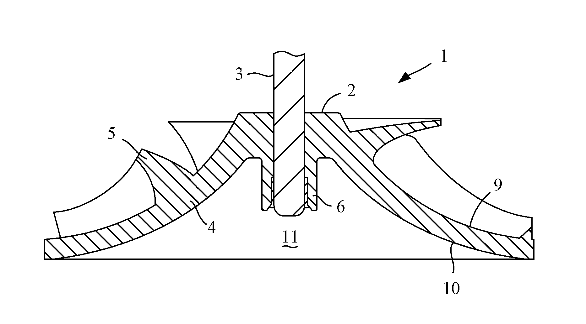
[0020]The rotor 1 of FIGS. 1 and 2 comprises an impeller 2 secured to a shaft 3.

[0021]The impeller 2 comprises a hub 4, a plurality of blades 5, a boss 6, a bore 7 and a counterbore 8.

[0022]The hub 4 has an aerodynamic upper surface 9 on which the blades 5 are provided, and a lower surface 10 that defines a recess 11 in the underside of the hub 4.

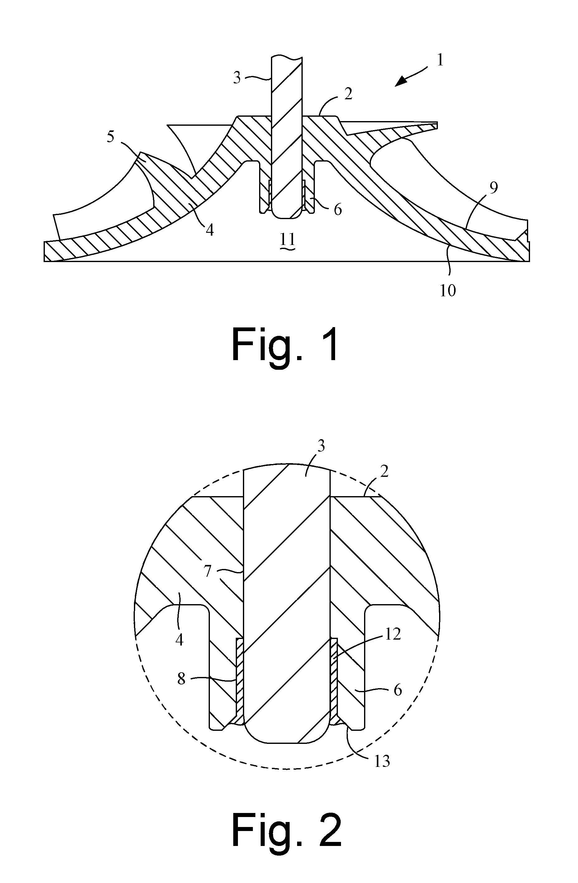
[0023]The boss 6 is cylindrical in shape and extends axially from the center of the hub 4. More specifically, the boss 6 extends downward from the lower surface 10 of the hub 4 and into the recess 9.

[0024]The bore 7 extends axially through the center of the hub 4 and into an upper part of the boss 6. The counterbore 8 extends axially through the lower part of the boss 6. The bore 7 and counterbore 8 thus provide an axial conduit through the impeller 2.

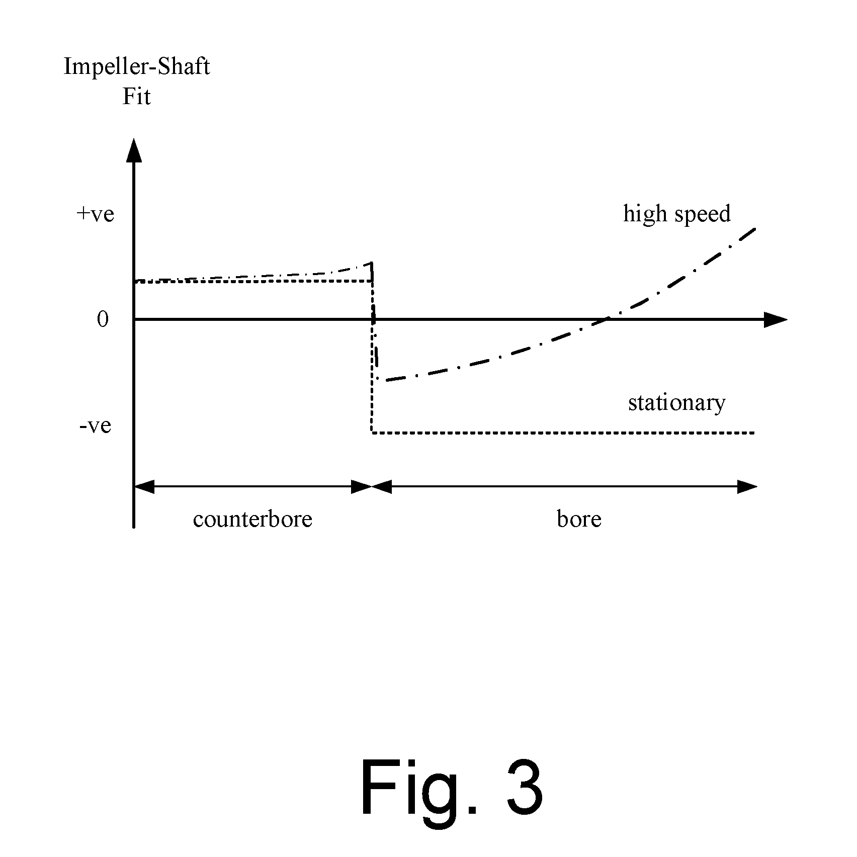
[0025]The shaft 3 is received within the bore 7 and the counterbore 8. The bore 7 and counterbore 8 are sized such that the shaft 3 forms an interference fit with the bore 7 and a clearance fi...


PUM


Abstract

A rotor that includes an impeller secured to a shaft. The impeller has a bore and a counterbore. The shaft forms an interference fit with the bore and is adhered to the counterbore. A method of manufacturing the rotor is also described.

Description

REFERENCE TO RELATED APPLICATIONS[0001]This application claims the priority of United Kingdom Application No. 1102132.6, filed Feb. 8, 2011, the entire contents of which are incorporated herein by reference.FIELD OF THE INVENTION[0002]The present invention relates to a rotor for a turbomachine.BACKGROUND OF THE INVENTION[0003]The rotor of a turbomachine typically comprises an impeller secured to a shaft. The impeller may be secured to the shaft by interference fit, which provides a cost-effective means of securement. As the rotor rotates, radial stresses cause the bore of the impeller to expand. As a result, the interference fit between the impeller and shaft decreases. At relatively high speeds, the expansion of the bore may be such that the interference fit is no longer able to transmit the required torque between the shaft and the impeller. In order to avoid this situation, the interference fit between the impeller and the shaft, when stationary, may be increased. However, the re...

Claims


Application Information

Patent Timeline
IPC IPC(8): F04D29/34B21D53/78
CPCF04D29/02F04D29/20Y10T29/49316F04D29/026F04D29/263F05D2300/43F16D1/068Y10T29/49321F04D29/26F04D29/28
Inventor DYMOND, NIGEL YOUATTIONS, DAVID
Owner DYSON TECH LTD
Why Eureka
Try Eureka