Burner for a turbine

a turbine and burner technology, applied in the combustion process, hot gas positive displacement engine plants, lighting and heating apparatus, etc., can solve the problems of reducing the formation of nox (particularly thermal nox), and achieve the effect of simple and fast fuel exchange, low emissions, and simple exchangeability of fuel supply pipes

Inactive Publication Date: 2012-09-13
MAN ENERGY SOLUTIONS SA
View PDF25 Cites 9 Cited by
  • Summary
  • Abstract
  • Description
  • Claims
  • Application Information

AI Technical Summary

Benefits of technology

[0009]Due to the fact that the injection of fuel into the burner according to the invention is carried out inside the inlet passages or air channels of the swirler through individual fuel supply pipes with a directional component extending transverse to the oxidant flow direction, an extremely homogeneous premixing of the fuel-oxidant mixture, e.g., a fuel-air mixture, to be introduced into the combustion chamber of the burner is achieved in a simple and economical manner.
[0032]Through the use of the central fuel supply pipes in the inlet passages of the swirler, optimal mixtures of fuel (e.g., combustible gas) and oxidant (e.g., air) are possible. Low emissions can be achieved in this way. At the same time, the individual configuration of fuel output openings and / or positioning of the fuel supply pipes makes it possible to respond to locally different oxidant distributions, e.g., locally different air distributions. The solution according to the invention is very economical due to the central exchangeable fuel supply pipes.

Problems solved by technology

In particular, this reduces the formation of NOx (particularly thermal NOx).

Method used


Image

  • Burner for a turbine
  • Burner for a turbine
  • Burner for a turbine

Examples


Embodiment Construction

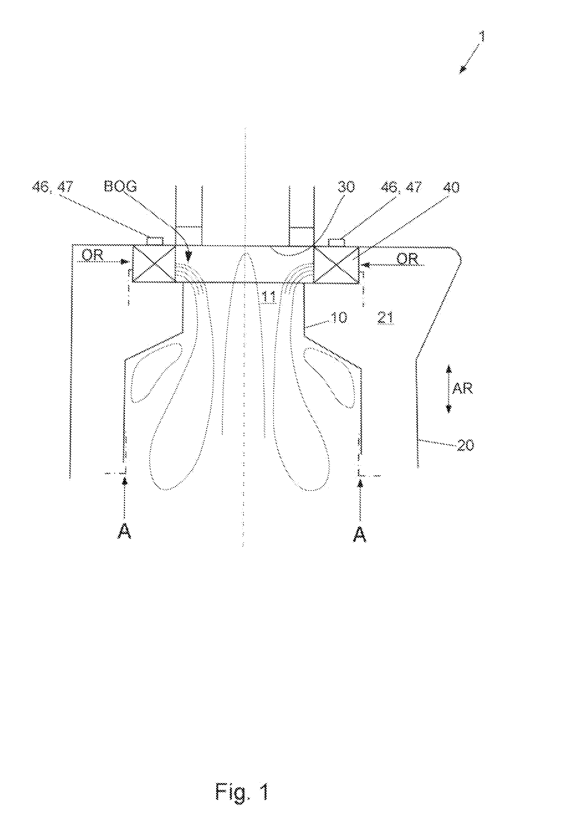
[0038]FIG. 1 shows the construction of a burner 1 of a gas turbine (not shown in its entirety) according to an embodiment of the present invention.

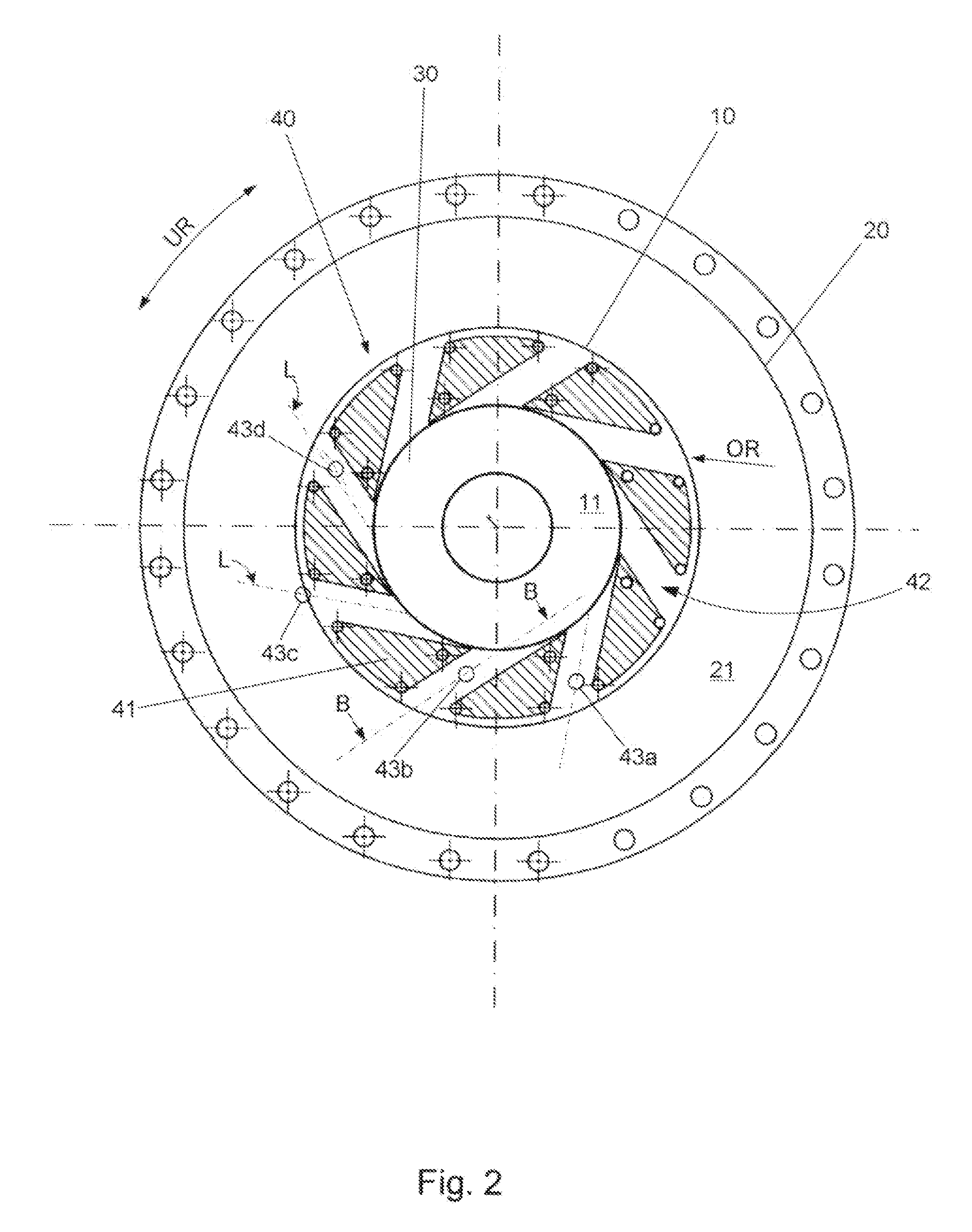
[0039]The burner 1 has a flame tube 10 in which a combustion space 11 is formed and a tubular casing 20 which encloses the flame tube 10 from radially outward at a predetermined distance therefrom so that an oxidant collection chamber 21 is formed between the flame tube 10 and casing 20.

[0040]Combustible gas is provided as fuel for the burner 1, and atmospheric air is provided as oxidant for the combustible gas. This atmospheric air is compressed by a compressor (not shown) and then fed to the oxidant collection chamber 21.

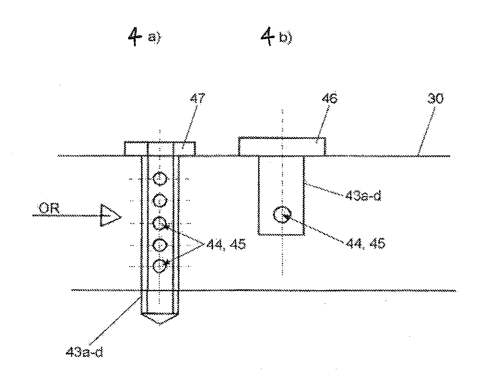
[0041]Further, the burner 1 has a burner bottom 30 which bounds the oxidant collection chamber 21 and combustion space 11 at an axial end of the burner 1 and a swirler 40 which is arranged axially between the flame tube 10 and burner bottom 30 axially adjoining the burner bottom 30 and radially adjoining the oxidant col...


PUM


Abstract

A burner for a turbine has a flame tube, a casing enclosing the flame tube forming an oxidant collection chamber, a burner bottom which bounds the oxidant collection chamber and the combustion space, and a swirler which has a plurality of guide vanes arranged so that the distances between the guide vanes form a plurality of radial inlet passages to the combustion space. A fuel supply pipe is provided in the inlet flow region of at least some of the inlet passages, which fuel supply pipe extends lengthwise through the respective inlet passage in an axial direction of the burner and traverse to an oxidant flow direction, and wherein each fuel supply pipe has in its wall at least one radial fuel output opening by which fuel can be mixed into the respective inlet passage with a directional component extending transverse to the oxidant flow direction.

Description

PRIORITY CLAIM[0001]This is a U.S. national stage of application No. PCT / DE2010 / 050074, filed on 28 Sep. 2010. Priority is claimed on the following application: Country: Germany, Application No.: 10 2009 054 669.3, filed: 15 Dec. 2009, the content of which is incorporated herein by reference.[0002]The present invention is directed to a burner for a turbine and particularly to a burner which is provided with a device for premixing oxidant and fuel for a turbine.BACKGROUND OF THE INVENTION[0003]Premix burners, as they are called, are used in turbines, e.g., gas turbines in order to achieve lower emissions. Through the use of premix technology, the process of mixing fuel and oxidant such as air is decoupled from, i.e., made antecedent to, the actual combustion process. Peak temperatures during combustion can be reduced in this way. At the same time, the retention time of the fuel-oxidant mixture (e.g., fuel-air mixture) in the reaction zone is shortened. In particular, this reduces the...

Claims


Application Information

Patent Timeline
Patent Type & Authority Applications(United States)
IPC IPC(8): F23R3/28
CPCF23R3/286F23R3/14
Inventor REISS, FRANKORTH, ULRICHHUITENGA, HOLGER
Owner MAN ENERGY SOLUTIONS SA
Why Eureka
Try Eureka