
Device and method for locally resolved control of a radiation dose

a local resolution and radiation dose technology, applied in the field of devices and methods for local resolution control of radiation doses, can solve the problems of large error, inability to accurately control the radiation dose, and difficulty in achieving local resolution, so as to achieve simple and economical manner

Inactive Publication Date: 2010-10-05
SIEMENS AG
View PDF18 Cites 10 Cited by
  • Summary
  • Abstract
  • Description
  • Claims
  • Application Information

AI Technical Summary

Benefits of technology

[0012]The object of the invention is to allow a locally resolved detection of the applied radiation dose in a simple and economical manner.
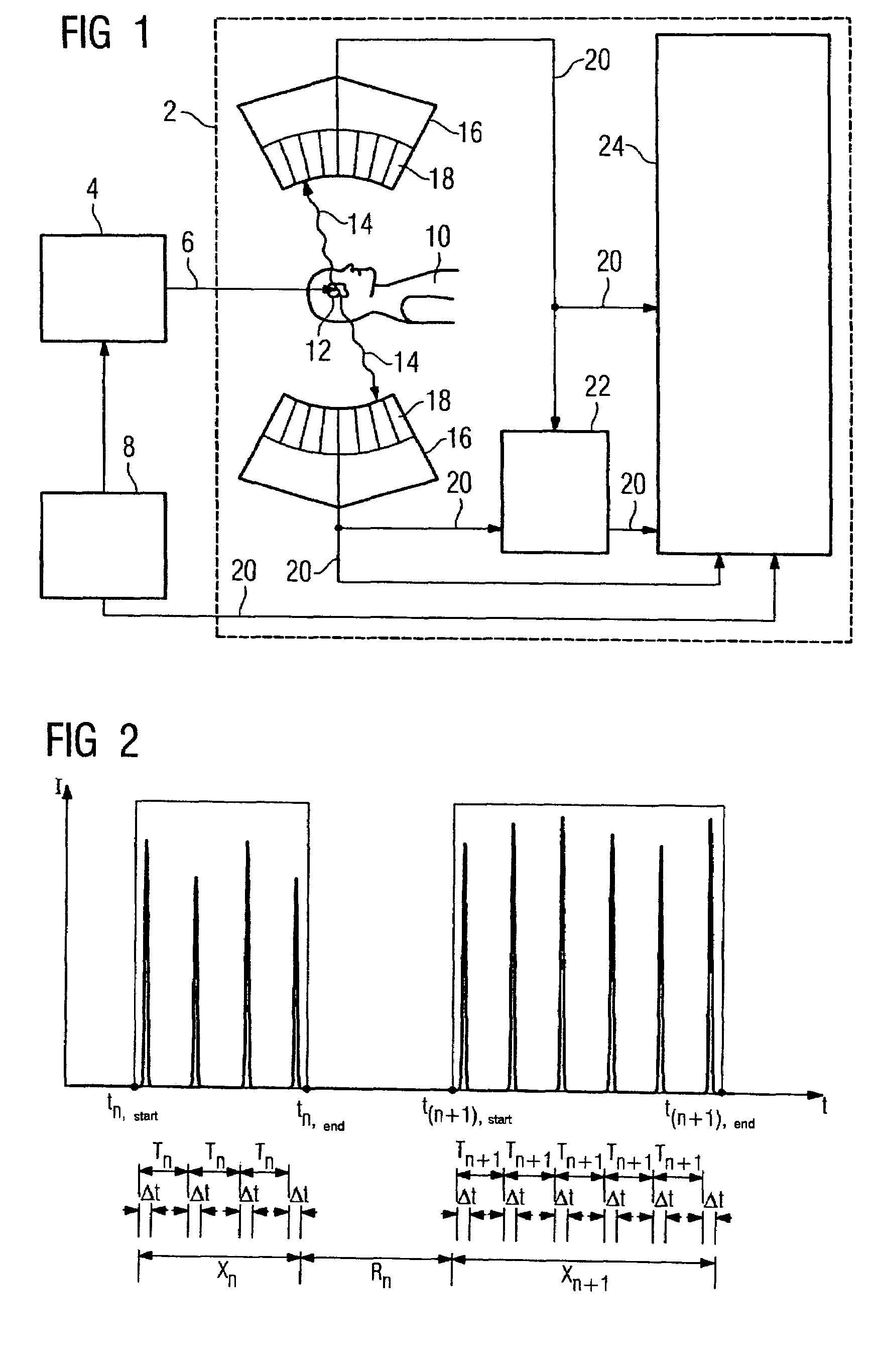
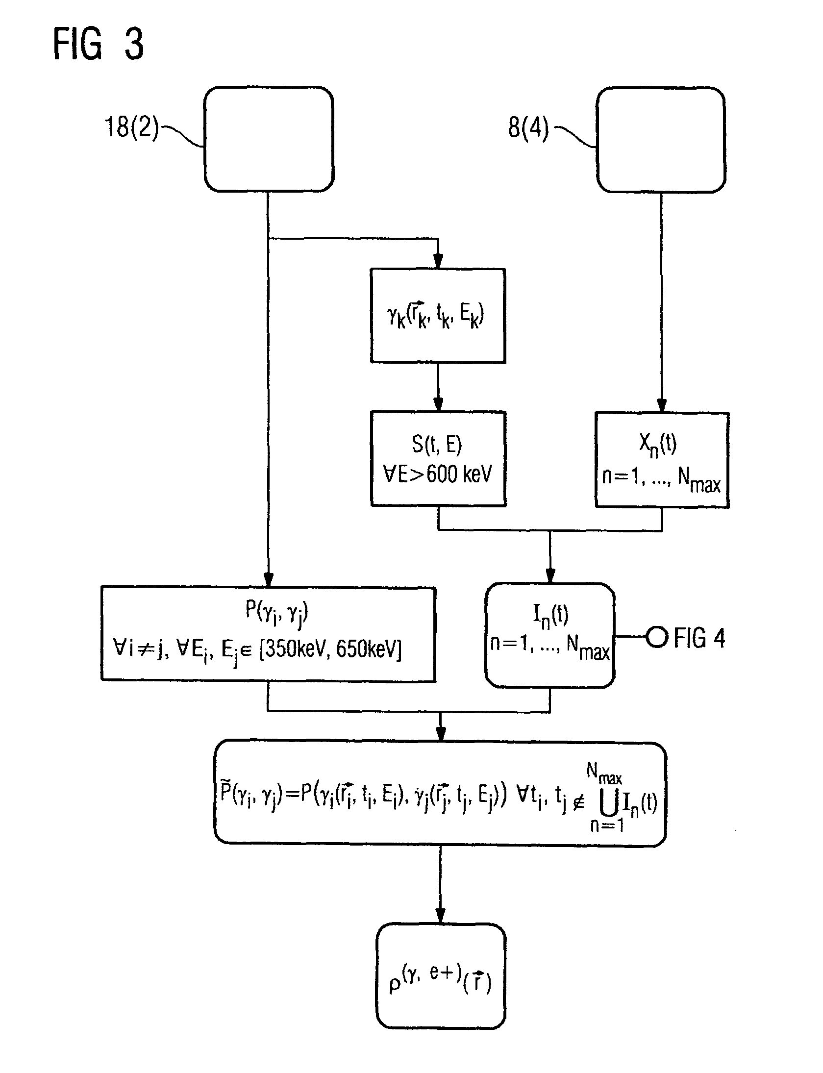
[0020]In an expedient variant the processing unit is set up to determine the time offset by forming a mathematical correlation function from the periodic function and the temporal pattern of the count rate of the characteristic decay events, said mathematical correlation function for example having the appearance of a convolution integral. The time offset of the radiation pulse sequence at the application site compared with the time of its generation is then clear from the maximum of the correlation function. The formation of a correlation function is a method known anyway in mathematics, which is easy to convert for programming purposes. It is thus possible to determine the time offset in a particularly simple manner.

Problems solved by technology

A problem arises during the evaluation of the measured x-ray quanta.
Since these beam delays only make up around 30 to 70% of the total beam exposure time, compared with the radiation pulse sequences, also referred to as beam extraction phases, and since positron decays are not taken into account during the beam extraction phases, measuring using positron emission tomographs is subject to relatively major error.
This error is perpetuated in the calculation of the radiation dose applied in a site-dependent manner.
This method also requires very complex and precise synchronization between the control signal of the particle accelerator and the positron emission tomograph.
Determination of the time intervals is however very complex in both instances.

Method used


Image

  • Device and method for locally resolved control of a radiation dose
  • Device and method for locally resolved control of a radiation dose
  • Device and method for locally resolved control of a radiation dose

Examples


Embodiment Construction

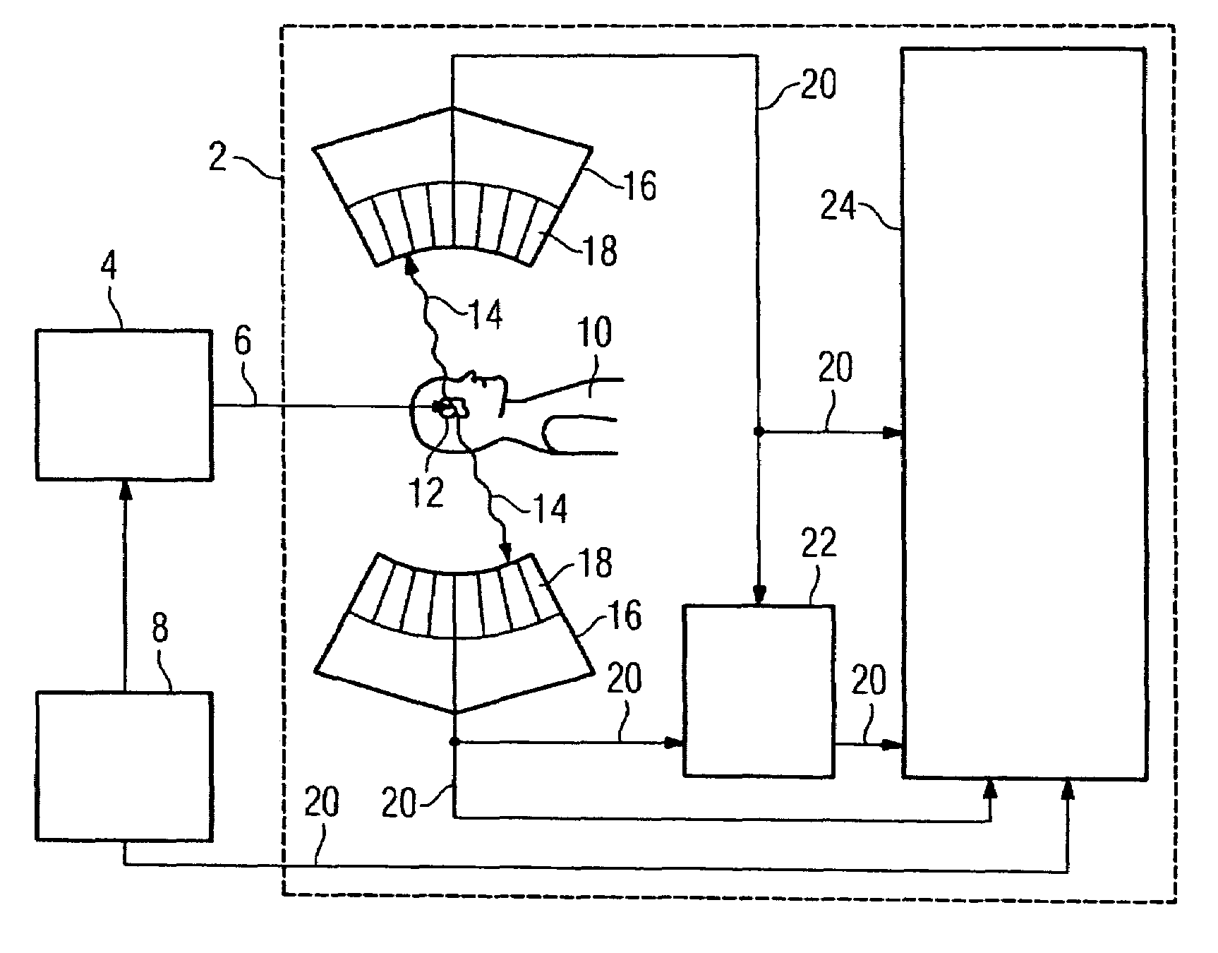
[0035]FIG. 1 shows a schematic diagram of a device for particle beam therapy, having a positron emission tomograph 2 for locally resolved control of an applied radiation dose. For particle beam therapy a particle accelerator 4 generates a pulsed particle beam 6. This pulsed particle beam 6 contains protons or ions. Its pulse sequence is predetermined by a control unit 8. The pulsed particle beam 6 is used to irradiate tumor tissue 12 in a person 10 in a specific manner. Radiation causes positron emitters to form at the application site, in other words within the tumor tissue 12 and these decay very quickly, emitting a positron in each instance. Each of these positrons annihilates with an electron of an adjacent atom, in that two x-ray quanta 14 fly out from the annihilation site in opposing directions, in other words at a 180° angle. The two x-ray quanta 14 are registered respectively by one of the detectors 18 disposed in a circle round the application site and held by a holding de...


PUM


Abstract

A device for locally resolved control of a radiation dose applied with a pulsed particle beam in particle beam therapy, with a processing unit, which is set up to detect continuously a count rate of x-ray quanta measured with a positron emission tomograph and to determine the applied radiation dose from the pattern of the measured count rate, by determining by computation from the measured pattern of the count rate the time intervals, in which an interaction of the particle beam takes place at the application site and by rejecting these time intervals for the determination of the applied radiation dose.

Description

CROSS REFERENCE TO RELATED APPLICATIONS[0001]The present application claims the benefit of the provisional patent application filed on May 23, 2006, and assigned application No. 60 / 802,870. The present application also claims priority of German application No. 10 2006 024 243.2 filed on May 23, 2006. Both of the applications are incorporated by reference herein in their entirety.FIELD OF THE INVENTION[0002]The invention relates to a device and method for locally resolved control of a radiation dose applied with a pulsed particle beam in particle beam therapy.BACKGROUND OF THE INVENTION[0003]In particle beam therapy a tumor in a patient is irradiated with protons or ions in a pulsed manner. This pulsed proton or ion radiation is supplied in this context by a particle accelerator, for example a synchrotron. Radiation pulse sequences, having an infinite number of radiation pulses, alternate here with beam delays. The radiation parameters here are set in such a manner that the greatest ...

Claims


Application Information

Patent Timeline
Patent Type & Authority Patents(United States)
IPC IPC(8): A61N5/00
CPCA61N5/1048A61N2005/1052A61N2005/1087
Inventor BRAESS, HENNING
Owner SIEMENS AG
Learn More