Method for Operating an Electromotive Drive

a technology of electromotive drive and drive shaft, which is applied in the direction of relays, open-end spinning machines, mechanical equipment, etc., can solve the problems of mechanical damage to the drive, premature wear of the catch bearing, mechanical damage to the catch bearing and/or the entire inner drive assembly, etc., and achieves simple and economical operation and increased operating safety.

Active Publication Date: 2009-05-28
SAURER SPINNING SOLUTIONS GMBH & CO KG
View PDF8 Cites 9 Cited by
  • Summary
  • Abstract
  • Description
  • Claims
  • Application Information

AI Technical Summary

Benefits of technology

[0007]The object of the present invention is therefore to provide a method for operating an electromotive drive, which in a simple and economical manner allows the determination and monitoring of the bearing air gap during stationary operation, as well as an electromotive drive, which is distinguished by increased operating safety.
[0009]During operation, an output signal generated by the control device to maintain the force-free floating state is input. The bearing air gap is calculated here by evaluating the output signal. The values determined from the evaluation of the output signal for the bearing air gap are compared with the limit values determined at the outset. When the limit values determined for the bearing air gap have been passed, the electromotive drive is switched off, so damage to the catch bearings or the entire inner drive assembly can be substantially avoided.
[0011]The substantial advantage of the method according to the invention is that disturbing or process forces occurring, which exert an axially directed force on the rotor and thus displace it from its force-free floating position (neutral position), can be compensated by a corresponding activation of the control device up to an instant at which the initially determined limit values of the spacing of the bearing air gap are passed, which leads to the switching off of the electromotive drive and therefore to an increase in the operating safety.
[0013]In this case, the predeterminable limit values may be established below the initially determined extreme values. In this manner, it may be ensured that in the case of a switching off, up to the instant of the switching off, an adequate safety spacing from the catch bearings is ensured. For this purpose, the limit value may be determined from the difference in the size of the bearing air gap obtained using the measured extreme values and a predeterminable reduction to increase the operating safety, for example up to a third of the size of the bearing air gap.
[0015]It can advantageously be provided, that prior to the run-up of the rotor, a reference value of a working point of the rotor in the floating state can be determined, so a working point which is established during stationary operation and differs from this reference value is determinable. It can thus be achieved that a weakening which becomes established of the bearing means used for contactless mounting, which may occur during ageing of the drive, becomes determinable. For this purpose, it is provided that the reference value can be determined from the average value of the spacing of the rotor from the catch bearings. This procedure allows assessment of the state of the bearing means during running operation.
[0017]Furthermore, the switching off of the electromotive drive can be brought about by a defined deviation of the working point being adjusted from the reference value in order to rule out damage to the catch bearings or the entire inner drive assembly. Moreover, it may be provided that the deviation of the working point being adjusted from the reference value is signaled in an appropriate manner to promptly draw attention to wear indications of this type.

Problems solved by technology

The rotor contacting the catch bearings involves the risk that the kinetic energy of the rotor being released will lead to premature wear of the catch bearings through to mechanical destruction of the catch bearings and / or the entire inner drive assembly.
A disturbing force of this type may result, in rotors which are used for textile machines, for example, from a thread accumulation being deposited on the shaft of the rotor between the bearing magnets and exerting an axially directed force on the rotor and displacing it from the force-free floating state occurring in stationary operation in the direction of one of the catch bearings.
This disturbing force is counteracted by corresponding activation of a control device, with the result that with a lack of knowledge of the remaining bearing air gap, the rotor may be pressed against one of the catch bearings and this may result in damage to the drive.
The use of absolutely measuring gap sensors is disadvantageous in that absolutely measuring gap sensors with a small offset error and very high measuring precision are expensive and require a high outlay for adjustment.
The constantly present offset error of the gap sensors means that the rotor is displaced from its force-free floating state.
The use of more economical gap sensors is linked with the disadvantage that these have a larger offset error.
On the one hand, with large offset errors of the gap sensors a very large current flows, which in some circumstances can exceed the power limits of the control device.
On the other hand, a position displacement of the rotor from its force-free floating state takes place, so the catch bearings may be approached too closely or there may even already be contact in the extreme case.

Method used


Image

  • Method for Operating an Electromotive Drive
  • Method for Operating an Electromotive Drive

Examples


Embodiment Construction

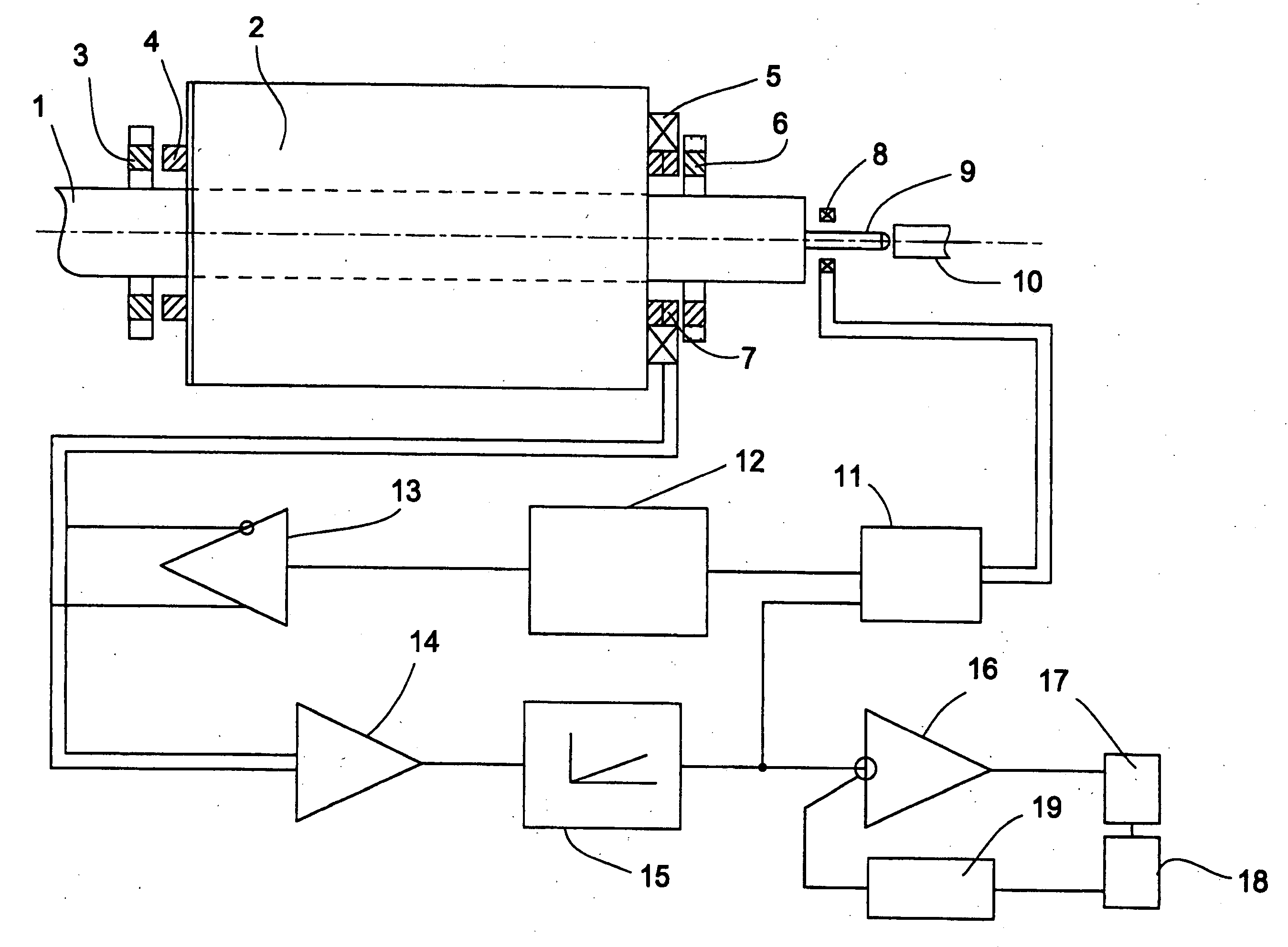
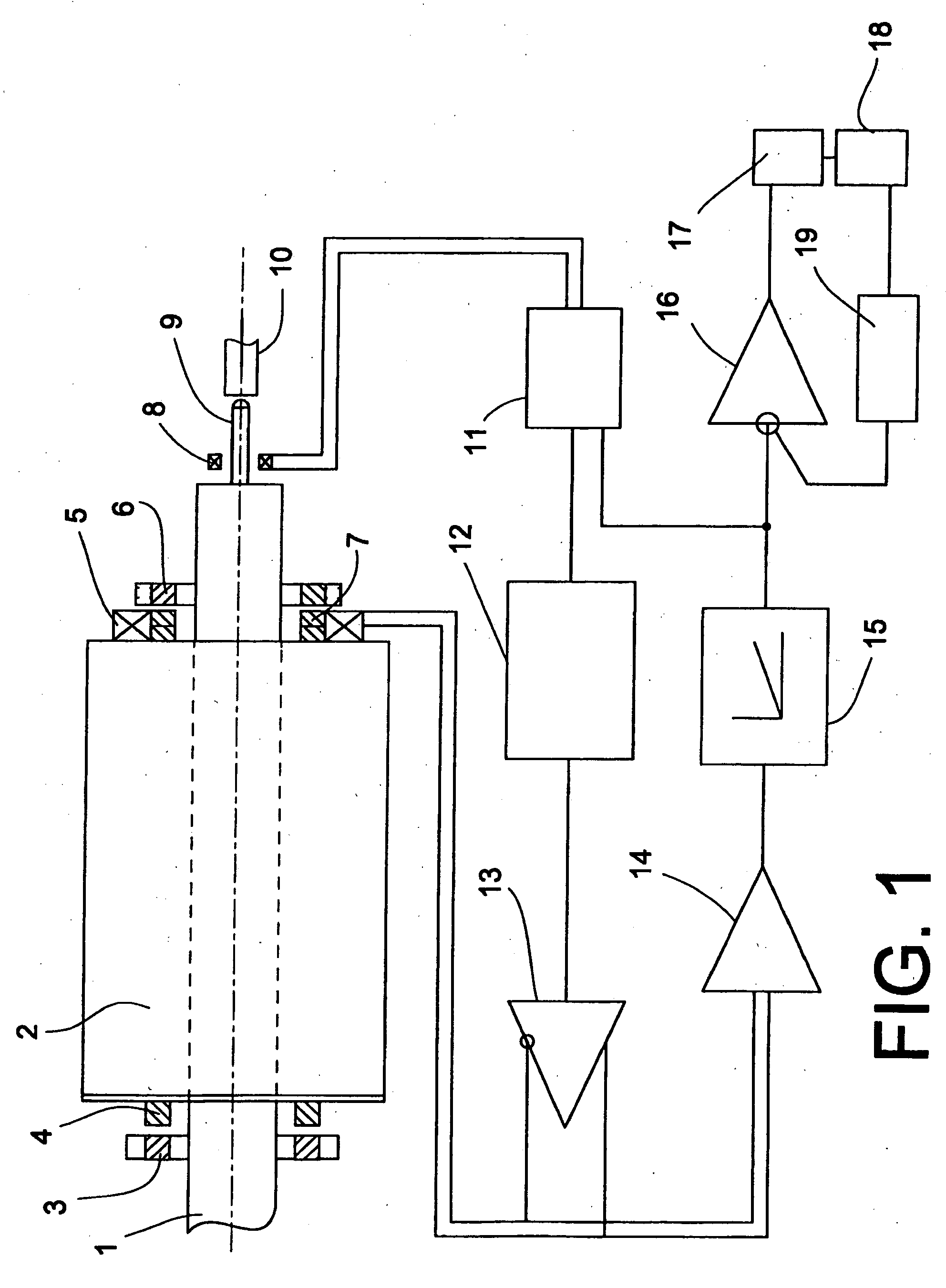
[0027]The view in FIG. 1 shows a bearing arrangement of an electromotive drive, in particular for a textile machine. The electromotive drive may be designed as the individual drive of a spinning mechanism, which is used as the drive for a contactlessly mounted rotor 1. The rotor 1 is designed as the rotor of the electromotive drive and is contactlessly supported in the radial and axial direction in the mounting designed as a magnetic bearing arrangement. The magnetic bearing arrangement inter alia comprises bearing magnets 3, 4, 6, 7, designed as permanent magnets, which axially support the shaft of the rotor 1. To achieve a higher rigidity or damping of the mounting of the rotor 1, further active or passive magnets may be provided. However, the use of a gas bearing in combination with a magnetic bearing arrangement is also possible.

[0028]The electromotive drive also comprises two catch bearings 10 (of which only one is shown in FIG. 1), which are used for the axial support of the r...


PUM

PropertyMeasurementUnit
speedaaaaaaaaaa
widthaaaaaaaaaa
electrical energyaaaaaaaaaa

Abstract

A method for operating an electromotive drive of a textile machine, comprising a contactlessly mounted rotor and catch bearings. The rotor rests on one catch bearing prior to initial operation, and is spaced therefrom by an air gap during stationary operation. A control device allows the rotor to be held in a force-free floating state during stationary operation. The method executes the following steps: (a) inputting an output signal from the control device for maintaining the force-free floating state during operation; (b) calculating the air gap by evaluating the output signal; (c) comparing the calculated value with predetermined limit values; and (d) deactuating the drive when the limit values are passed. The control device comprises a position sensor with at least one sensor coil, at least one actuator coil, a position controller and an integrator, at which the output signal is obtained to determine the air gap.

Description

CROSS-REFERENCES TO RELATED APPLICATIONS[0001]This application claims the benefit of German patent application DE 10 2005 032 184.4, filed Jul. 9, 2005, herein incorporated by reference.BACKGROUND OF THE INVENTION[0002]The present invention relates to a method for operating an electromotive drive as well as to an electromotive drive for carrying out such method.[0003]When using a contactlessly mounted rotor, which is configured as a rotor of an electromotive drive revolving at a high rotational speed, it is of particular interest to prevent the rotor contacting the catch bearings due to external process and disturbing forces acting on it. The rotor contacting the catch bearings involves the risk that the kinetic energy of the rotor being released will lead to premature wear of the catch bearings through to mechanical destruction of the catch bearings and / or the entire inner drive assembly.[0004]Knowledge of the spacing of the bearing air gaps is sensible in particular in the case of...

Claims


Application Information

Patent Timeline
Patent Type & Authority Applications(United States)
IPC IPC(8): H02K7/09F16C39/06
CPCD01H4/12D01H4/14F16C32/0442F16C32/0476H02K7/09F16C32/0451F16C39/02F16C2231/00F16C2340/18F16C32/0412F16C32/0478
Inventor COENEN, NORBERTLINKE, MARCO
Owner SAURER SPINNING SOLUTIONS GMBH & CO KG
Why Eureka
Try Eureka