Door Closer With Free-Swing Function

Active Publication Date: 2012-09-20
DORMAKABA DEUT GMBH
View PDF12 Cites 3 Cited by
  • Summary
  • Abstract
  • Description
  • Claims
  • Application Information

AI Technical Summary

Benefits of technology

[0006]It is an object of one embodiment of the present invention to provide a door closer that has a very slender structure while being manufactured at low costs, and whic

Problems solved by technology

The tensioning of such closer springs whenever the door is opened cannot

Method used


Image

  • Door Closer With Free-Swing Function
  • Door Closer With Free-Swing Function
  • Door Closer With Free-Swing Function

Examples


first embodiment

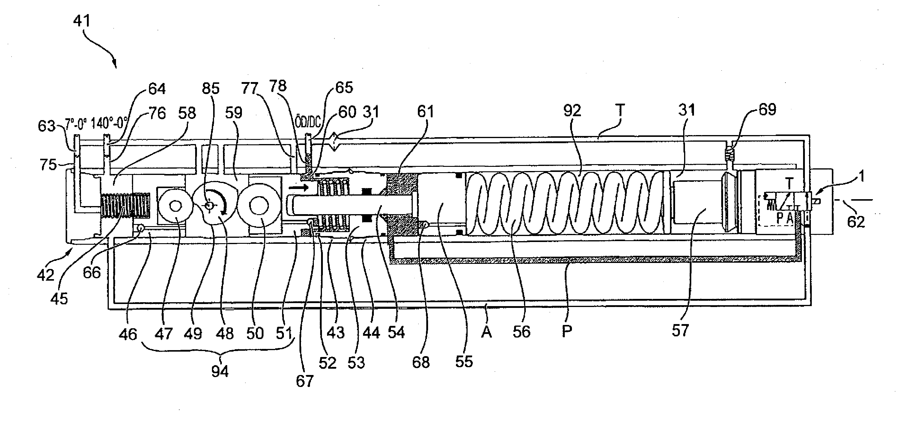
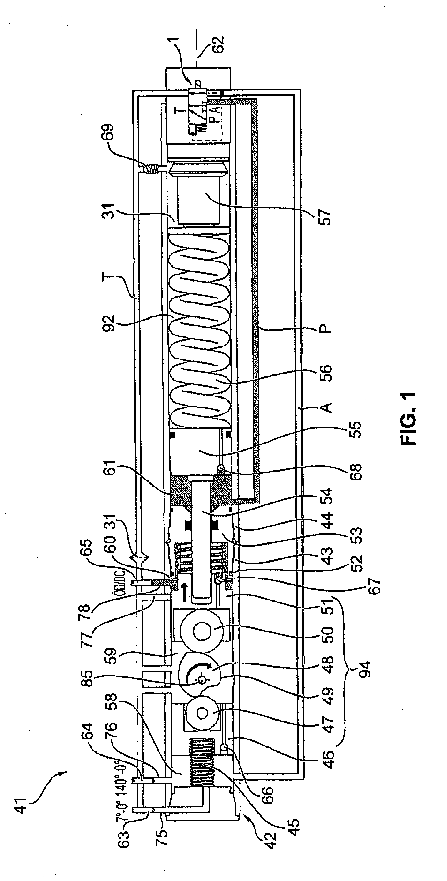
[0042]In the following, the basic structure as well as the hydraulic control and the function of a door closer 41 is explained with reference to FIG. 1.

[0043]The door closer 41 extends along a longitudinal door closer axis 62. The door closer 41 comprises a door closer housing 42 which in turn includes a first door closer housing part 43 and a second door closer housing part 44. In FIG. 1, the various hydraulic lines are shown to be outside the door closer housing 42. This illustration, however, is only given for facility of inspection. In practice, the hydraulic lines are integrated into the door closer housing 42. In the following, the structure of the door closer 41 along its longitudinal door closer axis 62 is explained from left to right. A first pressure spring 45 is supported against the door closer housing 42, in particular against a front face of the first door closer housing part 43. The first pressure spring 45 pushes a piston assembly 94. This piston assembly 94 is guid...

second embodiment

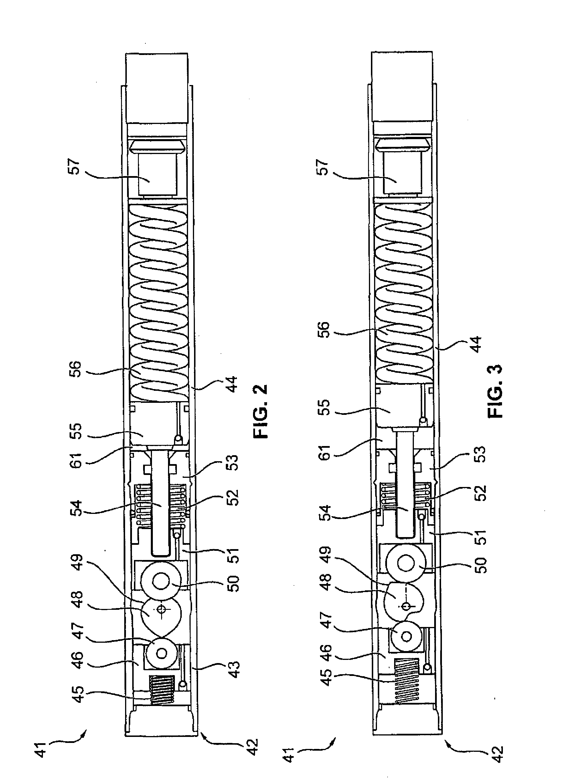
[0052]FIGS. 7 and 8 show a door closer 41 according to a Identical components or components identical in function are designated with identical reference numerals in all embodiments. FIG. 7 shows a door closer 41 during biasing of the closer spring 56. In FIG. 8, the lock compartment 61 is hydraulically blocked through the pressure line P. Consequently, the closer spring tension piston 55 and the closer spring 56 remain in their tensed positions. The piston assembly 94 and the door are freely swingable.

[0053]Apart from the differences described in the following, the second embodiment corresponds to the first embodiment: Contrary to the first embodiment, an additional piston 95 is arranged between the separating wall 53 and the piston assembly 94, in particular the opening piston 51, in the second embodiment. The additional piston 95 is fixedly connected to the piston rod 54 for transmitting a translational motion. The first front face 74 is formed frontally at the additional piston...

third embodiment

[0055]The piston assembly 94 proposed in FIGS. 9 and 10 replaces the piston assembly 94 of FIGS. 1 to 7, in particular the damper piston 46 including the first cam disc 47 and the opening piston 51 including the second cam disc 50. The output shaft 48 remains unchanged. Due to the use of the piston assembly 94 the first pressure spring 45 and the second pressure spring 52 are no longer required, however, they can be used as an addition.

[0056]FIG. 9 shows the piston assembly 94, wherein the damper piston 46 and the opening piston 51 are connected by a first tie rod 81, a second tie rod 82, a third tie rod 83 and a forth tie rod 84. The four tie rods 81 to 84 are arranged in parallel with the longitudinal door closer axis 62. In addition, the four tie rods 81 to 84 are arranged at four corners of a rectangle to be considered for the purpose of explanation only. The output axis 85 of the output shaft 48 passes through the section point of the diagonals of said rectangle. Due to this s...


PUM


Abstract

A door closer, in particular a hinge door closer, having a free-swing function, including a door closer housing, an output shaft to be connected to a door, a piston assembly connected to the output shaft and guided in the door closer housing, a closer spring, a piston rod adapted to connect the piston assembly to the closer spring, a free-swing assembly which is adapted to enable a translational motion of the piston assembly decoupled from the closer spring when the closer spring is locked, and which is embodied as a sliding-coupling which exclusively transmits compressive forces between the closer spring and the piston assembly, and a hydraulic lock compartment adapted to lock the closer spring.

Description

CROSS REFERENCE TO RELATED APPLICATIONS[0001]This is a U.S. national stage of application No. PCT / EP210 / 007255, filed on 30 Nov. 2010. Priority is claimed on German Application No.: 10 2009 056 265.6, filed 1 Dec. 2009 and German Application No.: 10 2010 013 853.3, filed 1 Apr. 2010, the contents of which are incorporated here by reference.BACKGROUND OF THE INVENTION[0002]1. Field of the Invention[0003]The invention relates to a door closer including an override function or free-swing-function referred to as free-swing-function.[0004]2. Description of Prior Art[0005]In the state of the art, a differentiation is made between door closers and door drives. In case of door closers, the door has to be opened manually by a person. During the opening process, energy is stored, e.g. in a closer spring, and the door closer is capable to close the door by using the stored energy. Contrary thereto, the door drive is an assembly which automatically opens and closes the door by an additional aux...

Claims


Application Information

Patent Timeline
IPC IPC(8): E05F3/10
CPCE05F3/104Y10T16/593F16K31/0627F16K31/0693E05Y2900/132Y10T16/2793Y10T16/27Y10T16/276Y10T16/2766Y10T16/2788Y10T16/2769Y10T16/2771Y10T16/2796Y10T16/56E05F3/223E05Y2201/638E05Y2600/634Y10T137/87917
Inventor BIENEK, VOLKER
Owner DORMAKABA DEUT GMBH
Why Eureka
Try Eureka