Illuminated Shovel Tool

Inactive Publication Date: 2012-10-11
BEST JASON
View PDF6 Cites 16 Cited by
  • Summary
  • Abstract
  • Description
  • Claims
  • Application Information

AI Technical Summary

Benefits of technology

[0022]Another object of the present invention is to provide a combination shovel tool and light source having a handle proximal end comprising an internal cavity that accommodates the securement of a removable, auxiliary light source for more detailed, shovel-independent inspections in low light and

Problems solved by technology

However, no shovel tool of similar structure and utility is disclosed that describes all elements of the present disclosure.
The Holder device is well adapted for sifting through material and inspecting the material being sift

Method used


Image

  • Illuminated Shovel Tool
  • Illuminated Shovel Tool
  • Illuminated Shovel Tool

Examples


Embodiment Construction

[0032]Reference is made herein to the attached drawings. Like reference numerals are used throughout the drawings to depict like or similar elements of the lighted shovel tool device. For the purposes of presenting a brief and clear description of the present invention, the preferred embodiment will be discussed as used for combining a directed illumination means with an excavation tool and further providing a cavity for securement of an auxiliary flashlight device. The figures are intended for representative purposes only and should not be considered to be limiting in any respect.

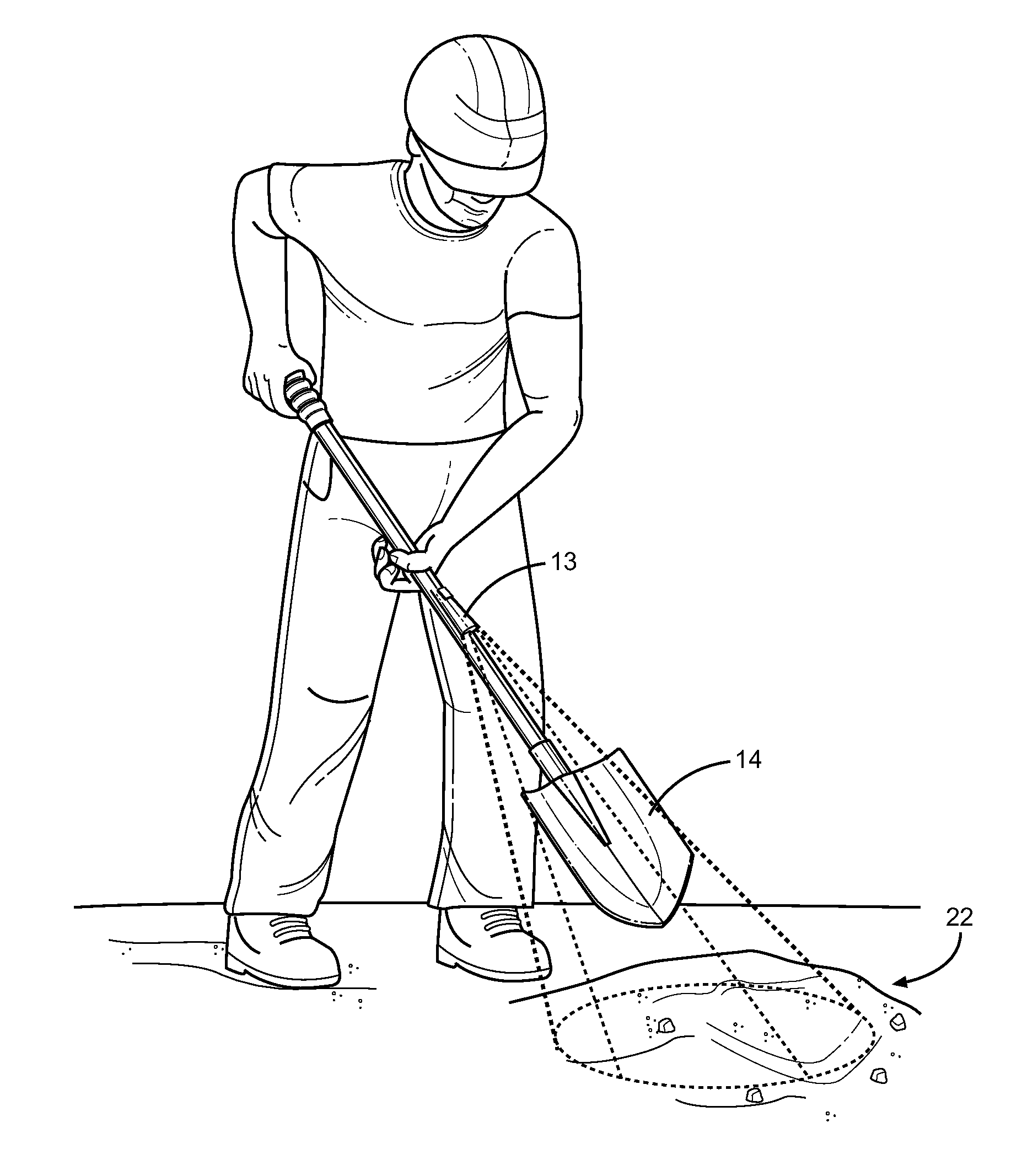
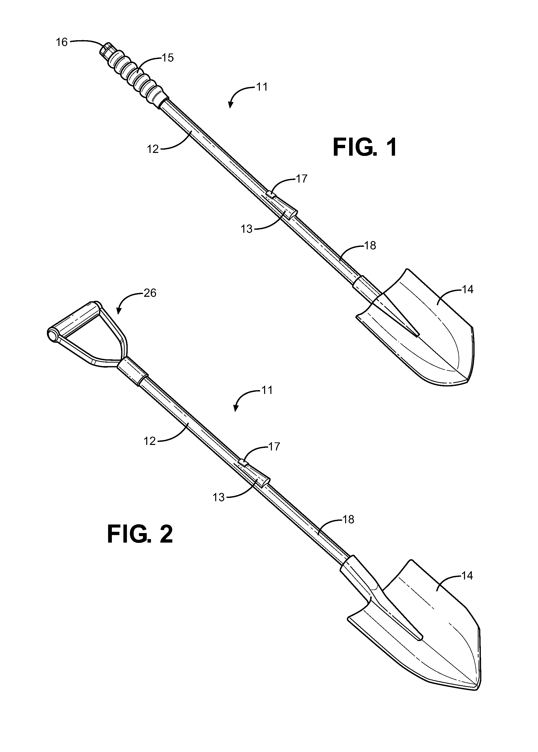
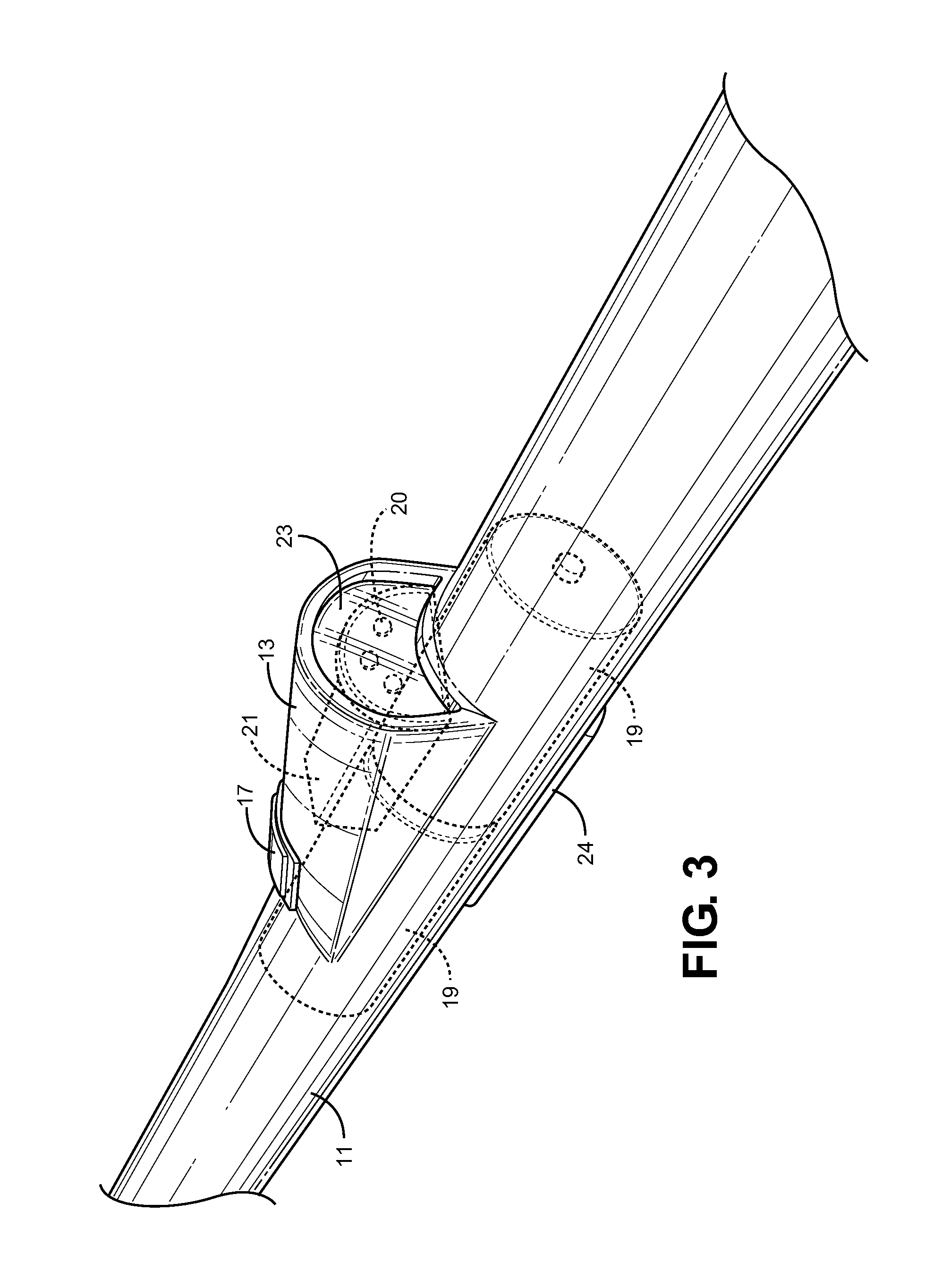
[0033]Referring now to FIGS. 1 and 2, there are shown perspective views of embodiments of the lighted shovel tool of the present invention. The tool comprises an elongated shaft 11 having a distal working end 18, a proximal handle end 12 and a central projection 13 that serves as a raised housing for a directed light source to be projected therefrom. The housing 13 is situated along the central region of t...


PUM


Abstract

Disclosed is a shovel tool implement having an imbedded illumination means and a means for storing an auxiliary light source in its handle. The tool comprises an elongated shaft having a proximal handle end and distal working end, the distal end preferably connecting to a shovel implement, the proximal handle end preferably having a slot in which to store a removable flashlight. At a location along the shaft length is provided an outward projection for housing a light source, power supply and on/off switch. The projection extends outward from the shaft and directs light towards the shovel working end, while the backside of the projection includes a removable cover for replacement of batteries and light source elements. The projection is situated such that normal handling of the shovel is not impeded, while the directed light allows a user to visualize a given work area in a low light environment.

Description

CROSS REFERENCE TO RELATED APPLICATION[0001]This application claims the benefit of U.S. Provisional Application No. 61 / 471,756 filed on Apr. 5, 2011, entitled “Shov Light.”BACKGROUND OF THE INVENTION[0002]1. Field of the Invention[0003]The present invention relates to hand tools with imbedded illumination means. More specifically, the present invention relates to a shovel tool having a hollow handle portion with a directed light source projection for illuminating a work area, and further a hollow handle proximal end for creating a housing for storing a detachable light source for general purposes in low light situations. The directed light source is one that is built into the shaft of the device or a location in which an handheld flashlight is secured and directed toward the shaft working end.[0004]It is well known that working with handheld tools in low light environments can be both dangerous and lead to mistakes in the work being conducted. Generally a large light source will be ...

Claims


Application Information

Patent Timeline
IPC IPC(8): A01D9/00
CPCA01B1/02F21V33/0084
Inventor BEST, JASON
Owner BEST JASON
Why Eureka
Try Eureka