Method of Determining Surface Pore Mouth Diameter Distribution of Porous Material

a technology of porous materials and pore mouths, which is applied in the direction of permeability/surface area analysis, suspension and porous material analysis, instruments, etc., can solve the problems of reducing the consumption of noble metals, pore size, and too low mechanical strength of pd membranes, and achieves simple operation, convenient for the detection of products, and easy construction

Inactive Publication Date: 2011-07-14
NANJING UNIV OF TECH
View PDF8 Cites 8 Cited by
  • Summary
  • Abstract
  • Description
  • Claims
  • Application Information

AI Technical Summary

Benefits of technology

[0021]3. The device used in the present invention is similar to that in the conventional bubble pressure method, is easy to construct, simple to operate, and suitable for the detection of products in scientific research and production processes.

Problems solved by technology

When a porous material is used in a filtration process, the most concerned issue is the pore size.
The commercial Pd membranes mostly have a thickness of 100 μm or greater, and further decrease in membrane thickness results in too low mechanical strength of the Pd membranes.
Moreover, the decrease of the membrane thickness also reduces the consumption of the noble metal.
The disadvantages of the composite Pd membrane are in that membrane defects may easily occur, and the larger the surface pore of the base is, the more the need for increasing the membrane thickness to control the membrane defects is [Mardilovich I P, Engwall E, Ma Y H. Dependence of hydrogen flux on the pore size and plating surface topology of asymmetric Pd-porous stainless steel membranes.
This method, however, also includes semi-permeable pores having no filtration function because it is used to detect the pore size distribution of the entire porous body, thus, the determination results have less value as reference for the actual filtration effect.
Moreover, the mercury porosimetry method is not suitable for filtration materials with a gradient pore size structure at all.
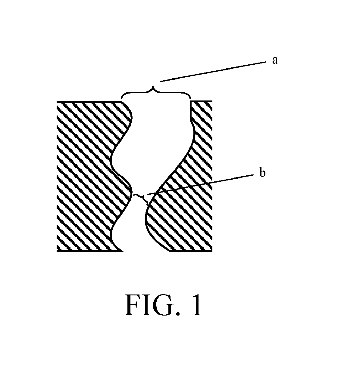
Except for the mercury porosimetry method, the above methods cannot provide the pore distribution information on the pore mouths, although they can measure the pore distribution of the pore throats of the porous materials and are of great value as reference for studying the filtration performance of these porous materials.
Direct observation with a microscope, for example, SEM, can be used in laboratory researches; however, this method has a small visual field, generally can only be used for observation of a tiny sample, and also is incapable of effectively detecting the largest pores.
Therefore, utility and value as reference of the method are very limited.

Method used


Image

  • Method of Determining Surface Pore Mouth Diameter Distribution of Porous Material
  • Method of Determining Surface Pore Mouth Diameter Distribution of Porous Material
  • Method of Determining Surface Pore Mouth Diameter Distribution of Porous Material

Examples


embodiment 1

[0028]i. A sample to be tested was a porous ceramic sheet having a diameter of 30 mm and a thickness of 2 mm. The sample was washed with 1 ml / L of a diluted HCl solution followed by DI water for about 5 min, and dried.

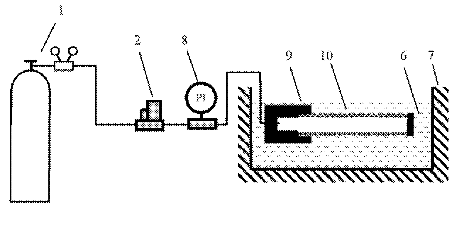
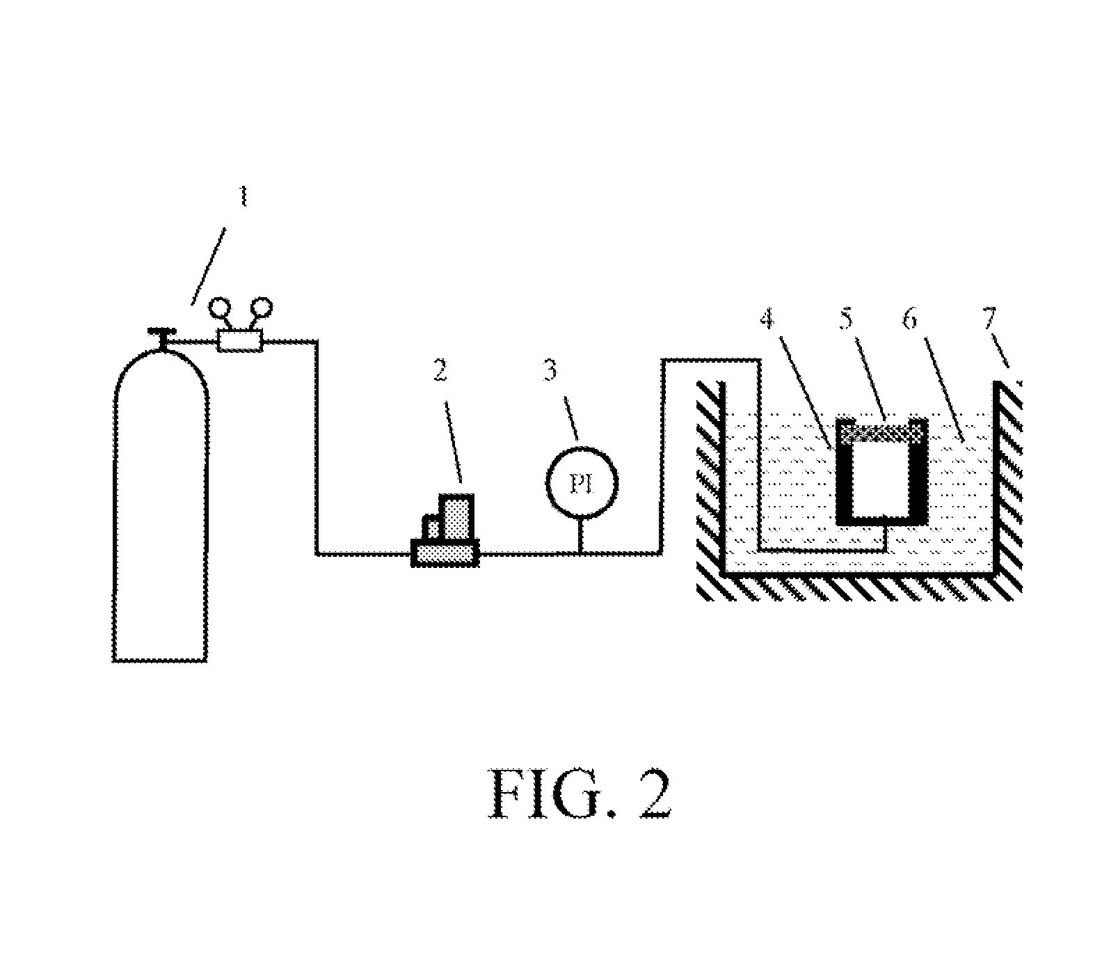
[0029]ii. The testing device, as shown in FIG. 2, was composed of a compressed gas cylinder (1), a mass flowmeter (2), a pressure gauge (3), a sample cell (4), a sample (5), and a water tank (7). The sample was placed into the sample cell (4) with the surface to be tested facing outwards, and two sides were respectively sealed by an annular silicone rubber pad with an outer diameter of 30 mm, an inner diameter of 10 mm and a thickness of 2 mm. The mass flowmeter (2) was regulated to gradually increase the gas flow rate from zero, and the gas flow rate and the pressure were recorded. When the flow rate was 5 L / min, the pressure was 184 kPa. At this time, the flow rate was plotted against the pressure to give a dry curve, and half of the flow rate was plotted against the...

embodiment 2

[0032]i. The sample was a SS-316L stainless steel membrane with a gradient pore structure having a diameter of 30 mm and a thickness of 2 mm, composed of a macroporous support and a pore-size controller with a thickness of 200 μm. The sample was washed with 1 ml / L of a diluted HCl solution, a 0.5 mol / L diluted NaOH solution, and then DI water for about 5 min, and dried.

[0033]ii. In this case, the membrane surface of the sample with a small pore size was to be measured. The determination for the data of the dry curve, half-dry curve, and wet curve were the same as those in the steps (ii), (iii) and (iv) of Embodiment 1, and the results are shown in FIG. 5. The mean pore size and the maximum pore size of the surface pore mouth of the membrane were measured to be 13.9 μm and 62.1 μm respectively.

[0034]iii. The mean pore size and the maximum pore size of the pore throat of the sample were measured in the same manner as the step (v) of Embodiment 1, and were 9.1 μm and 41.7 μm respective...

embodiment 3

[0035]i. The sample to be tested was the same as that in Embodiment 2, except that the support side of the sample was to be measured.

[0036]ii. Other operations were the same as those in Embodiment 2. The results are shown in FIG. 6. The mean pore size and the maximum pore size of the surface pore mouth of the support were measured to be 64.8 μm and 171.5 μm respectively.

[0037]iii. It can be seen from the results of Embodiments 2 and 3 that, the pore size of the support surface is much larger than that of the membrane surface for the same sample, which conforms to the actual situation of the sample, and indicates that this method is reasonable.


PUM

PropertyMeasurementUnit
thicknessaaaaaaaaaa
gas pressureaaaaaaaaaa

Abstract

A method of determining surface pore diameter distribution of a porous material is provided. A compressed gas is charged from backside of a sample of a porous body, a surface of the sample is immersed into a liquid wetting agent, and a gas pressure is regulated from high to low, such that pore mouths of the surface of the porous body are blocked by the wetting agent in an order from small to large pore sizes, and a gas flow rate is more rapidly decreased. When the pressure is decreased to a value, the gas flow rate is reduced to zero and the pressure at this time is corresponding to the largest pore mouth size of the surface of the porous body. The pore size distribution is determined by comparing the obtained gas pressure—flow rate curve (wet curve) with a gas pressure—flow rate curve (dry curve) obtained for the sample under a dry state. The pore size and the pore distribution are calculated based on the conventional bubble pressure method. The measurement of the surface pore distribution of the porous body is of great significance for investigating the support performance of the porous body.

Description

FIELD OF THE INVENTION[0001]The present invention relates to a method of determining surface pore diameter distribution of a porous material, which is used to measure a diameter of a pore mouth instead of a pore throat (narrowest point) of a pore passage.RELATED ART[0002]Porous materials have a number of excellent properties due to many internal pores, can be categorized into those with a uniform pore structure and those with a gradient pore structure, and have been widely applied in many processes of petrochemistry, food, construction, metallurgy, and aerospace industries, for example, for separation and purification, gas distribution, catalysis, silencing and damping, shielding, heat exchange, electrochemistry, and the like. In addition, in recent years, more attention has been paid to composite membranes formed by applying other functional materials on the surface of a porous base material. When a porous material is used in a filtration process, the most concerned issue is the po...

Claims


Application Information

Patent Timeline
Patent Type & Authority Applications(United States)
IPC IPC(8): G01N15/08
CPCG01N15/088
Inventor HUANG, YANYU, JIAN
Owner NANJING UNIV OF TECH
Why Eureka
Try Eureka