Amplifier Arrangement and Method for Operating an Amplifier Arrangement

Active Publication Date: 2012-10-25
AMS AG
View PDF4 Cites 7 Cited by
  • Summary
  • Abstract
  • Description
  • Claims
  • Application Information

AI Technical Summary

Benefits of technology

[0006]An object of the present invention is to provide an amplifier arrangement and a method for operating an am

Problems solved by technology

Moreover, biasing is not provided via a useful s

Method used


Image

  • Amplifier Arrangement and Method for Operating an Amplifier Arrangement
  • Amplifier Arrangement and Method for Operating an Amplifier Arrangement
  • Amplifier Arrangement and Method for Operating an Amplifier Arrangement

Examples


Example

DETAILED DESCRIPTION OF THE DRAWINGS

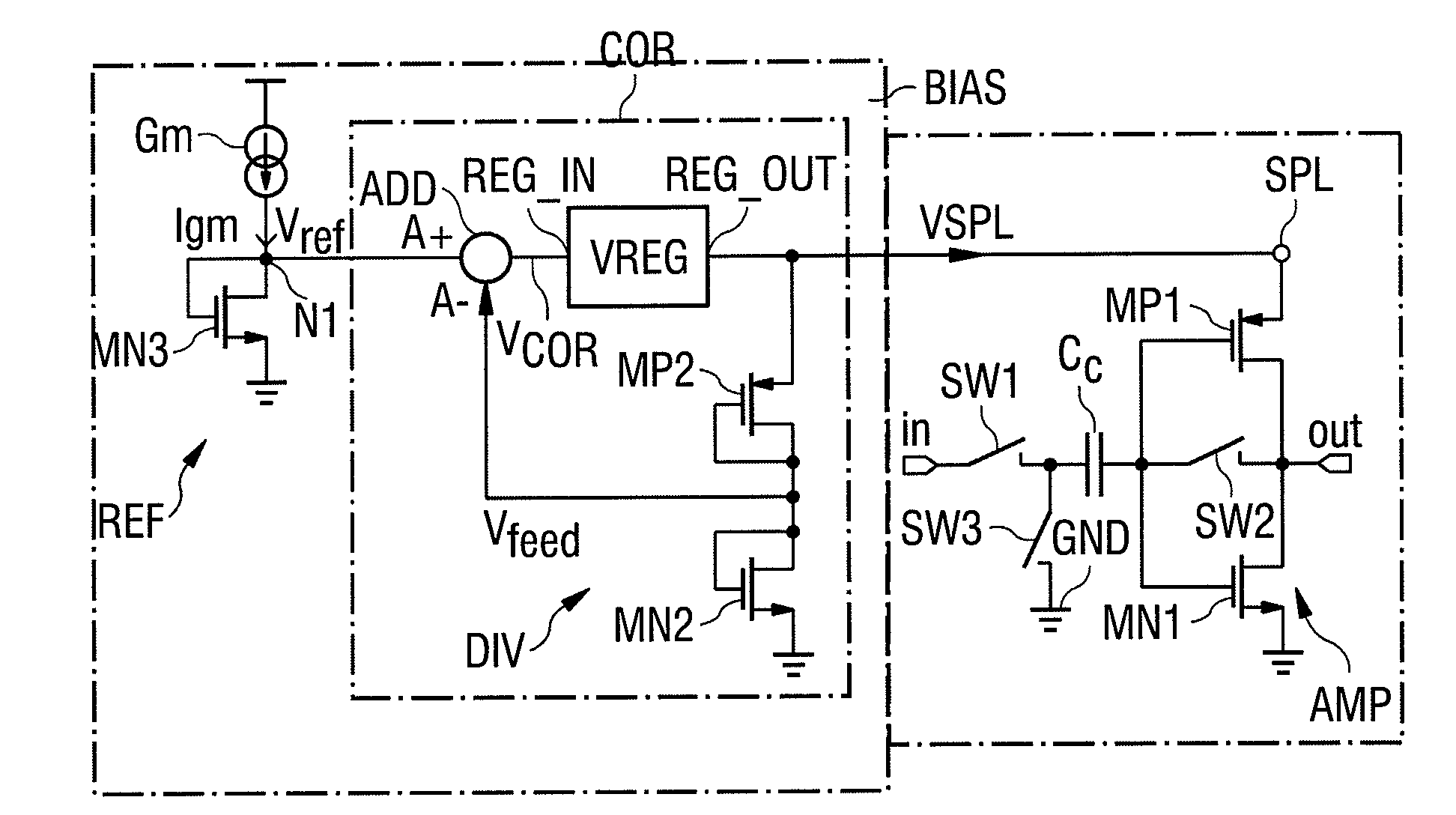
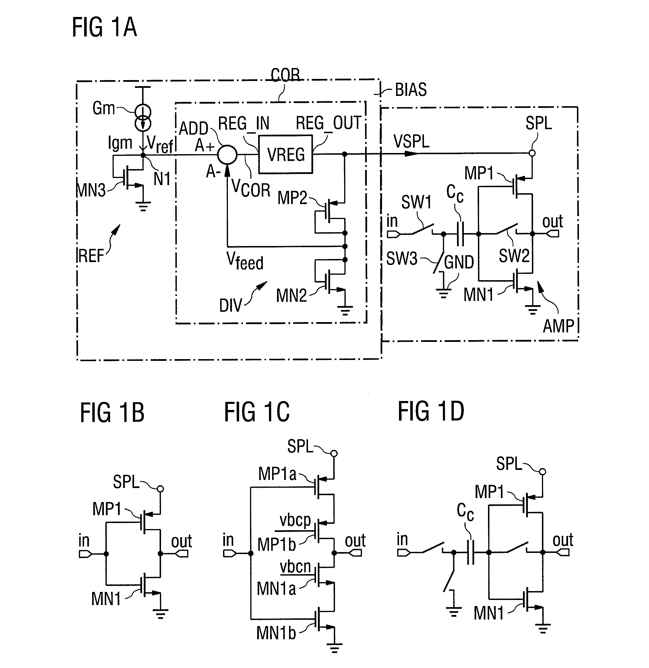
[0047]FIG. 1A shows an exemplary embodiment of an amplifier arrangement according to the invention. The circuit comprises an amplifier AMP and a bias circuit BIAS. The amplifier AMP and the bias circuit BIAS are connected to one another via a terminal SPL for a supply signal VSPL of the amplifier AMP.

[0048]The amplifier AMP in this example comprises an amplifier based on an inverter stage and including first transistors MN1, MP1, which are implemented, for example, as unipolar transistors. These first transistors MN1, MP1 are also connected to one another and to a capacitor Cc according to the principle of a switched-capacitor circuit. In this exemplary embodiment, the amplifier AMP further comprises an amplifier input “in” that can be connected to an amplifier output “out” via a series circuit having a first switch SW1, the capacitor Cc and a second switch SW2. The amplifier also has a third switch SW3, which is coupled between the first switch S...


PUM


Abstract

An amplifier arrangement comprising an amplifier (AMP) with a terminal (SPL) for a supply signal (VSPL) and a bias circuit (BIAS) for providing the supply signal (VSPL) at the terminal (SPL). The bias circuit holds an operating point (OP) of the amplifier (AMP) constant by means of the supply signal (VSPL). The bias circuit (BIAS) comprises a reference circuit (REF) for providing a reference signal (VREF) and a correction device (COR) by means of which the supply signal (VSPL) is regulated based on the reference signal (VREF) and a correction signal (Vfeed), the correction signal (Vfeed) being dependent on the operating point (OP) of the amplifier (AMP). A method for operating an amplifier arrangement is also described.

Description

RELATED APPLICATIONS[0001]This application claims the priority of German application no. 10 2011 014 843.4 filed Mar. 23, 2011, the entire content of which is hereby incorporated by reference.FIELD OF THE INVENTION[0002]The present invention relates to an amplifier arrangement and a method for operating an amplifier arrangement.BACKGROUND OF THE INVENTION[0003]Single-stage class-AB amplifiers are among the most effective amplifiers for SC circuits. Single-stage amplifiers have only one current path and achieve a high dynamic range in class-AB operation. SC circuits are driven according to the principle of switched capacitors and are also referred to as switched-capacitor circuits.[0004]A class-AB operation of an amplifier is classified by its operating point, among other things. Floating voltage sources or batteries are frequently used to suitably adjust the operating point. They typically comprise capacitors and must be charged periodically in charging cycles. Operation of the ampl...

Claims


Application Information

Patent Timeline
IPC IPC(8): H03F1/38H03F3/04
CPCH03F1/308H03F3/005H03F2200/555H03F2200/375H03F3/3028
Inventor CHRISTEN, THOMAS
Owner AMS AG
Why Eureka
Try Eureka