Counter-flow flame test table capable of accurately adjusting burner nozzles

A flame test and burner technology, which is applied to burners, gas fuel burners, combustion methods, etc., can solve the problems of difficulty in ensuring accuracy, flame asymmetry, and time-consuming, and achieves high accuracy, easy operation, and simple adjustment methods. Effect

Pending Publication Date: 2019-12-06
ANHUI UNIVERSITY OF TECHNOLOGY
View PDF0 Cites 0 Cited by
  • Summary
  • Abstract
  • Description
  • Claims
  • Application Information

AI Technical Summary

Problems solved by technology

In the prior art, regarding how to adjust the distance between the upper and lower nozzles, a detachable mounting frame is usually used to adjust the distance between the upper and lower nozzles by moving the upper and lower nozzle trays up and down. However, each adjustment needs to be disassembled and installed frame, and the pallet needs to be leveled, the whole process is very complicated and time-consuming, and the accuracy is difficult to guarantee
[0004] Aiming at the problem of how to align the upper and lower nozzles, in the prior art, a horizontal adjustment platform is usually used to achieve the alignment of the upper and lower nozzles. However, when the traditional horizontal adjustment platform adjusts the horizontal position of the nozzle, the horizontal adjustment platform cannot be continuously adjusted, resulting in up and down hedging The nozzles are difficult to align, and the flame of the lower nozzle cannot cover the upper nozzle symmetrically, resulting in an asymmetrical flame, which makes it difficult to analyze its flame characteristics
[0005] Therefore, according to the above analysis, the flame test device in the prior art has the problem that the upper and lower nozzles are difficult to accurately adjust the distance and difficult to align

Method used


Image

  • Counter-flow flame test table capable of accurately adjusting burner nozzles
  • Counter-flow flame test table capable of accurately adjusting burner nozzles
  • Counter-flow flame test table capable of accurately adjusting burner nozzles

Examples


Embodiment Construction

[0039] The present invention will be further described below in conjunction with embodiment and accompanying drawing.

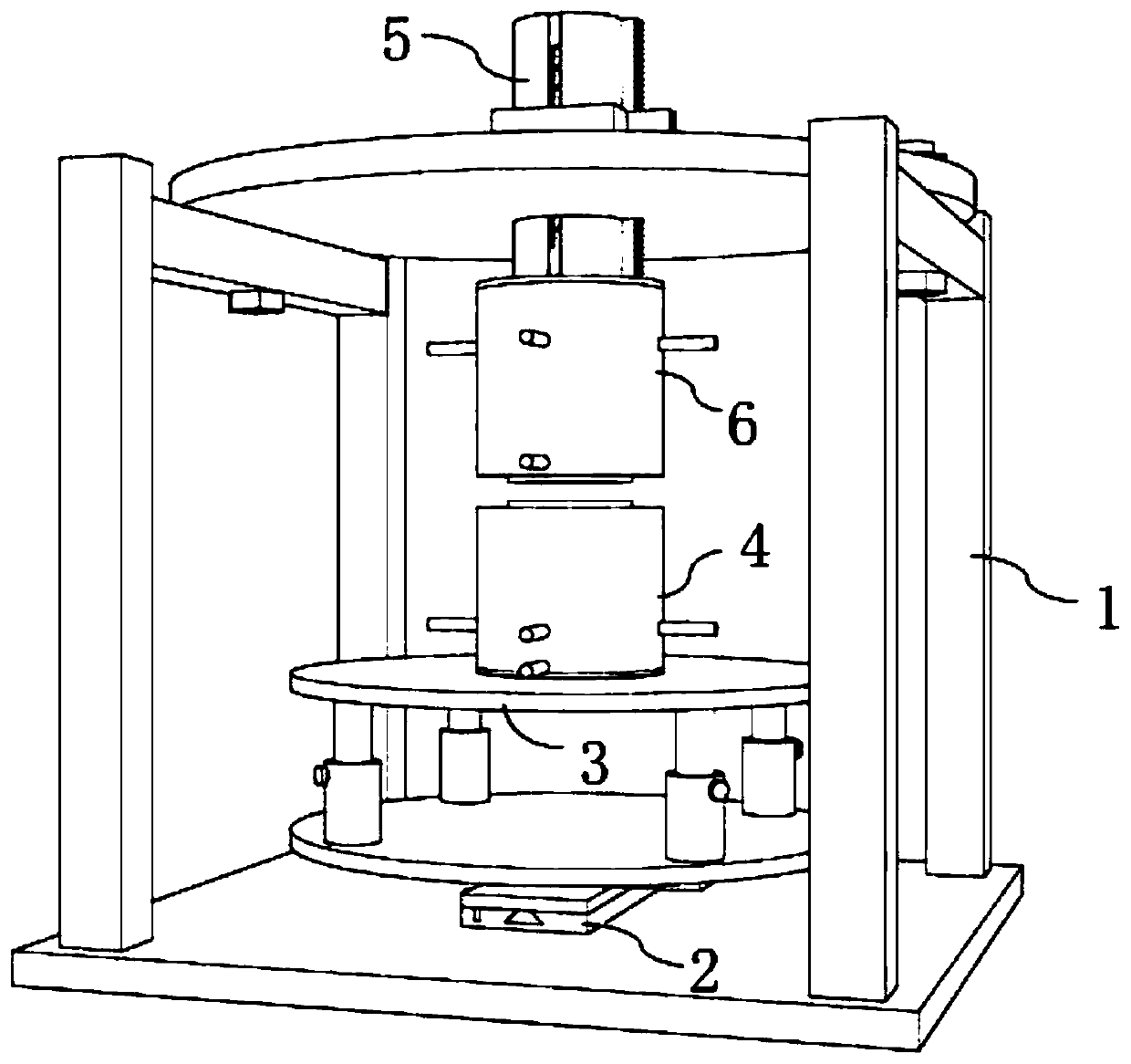
[0040] Such as figure 1 As shown, the flame test bench of the present invention includes an installation stand 1, a horizontal adjustment platform 2 arranged on the bottom plate of the installation stand 1, a lower burner support device 3 arranged on the horizontal adjustment platform 2, a set The lower opposite burner 4 on the lower burner supporting device 3, the upper burner adjustment device 5 passing through the top plate of the installation stand 1, and the upper opposite burner arranged at the lower end of the upper burner adjustment device 5 6. The nozzle of the lower counter burner 4 is opposite to the nozzle of the upper counter burner 6 .

[0041] Mounting stand 1 is mainly used for installing and fixing other components. Mounting stand 1 includes a base plate, a column arranged on the base plate, and a top plate arranged on the top of the column,...


PUM


Abstract

The invention discloses a counter-flow flame test table capable of accurately adjusting burner nozzles, and belongs to the field of counter-flow flame test devices. The counter-flow flame test table comprises a mounting rack, a horizontal adjusting platform arranged on a bottom plate of the mounting rack, a lower burner supporting device arranged on the horizontal adjusting platform, a lower counter-flow burner arranged on the lower burner supporting device, an upper burner adjusting device that penetrates through a top plate of the mounting rack, and an upper counter-flow burner arranged at the lower end of the upper burner adjusting device, wherein the nozzle of the lower counter-flow burner is opposite to the nozzle of the upper counter-flow burner. The counter-flow flame test table canaccurately adjust the distance between the nozzle of the upper counter-flow burner and the nozzle of the lower counter-flow burner, and can align the nozzle of the upper counter-flow burner with thenozzle of the lower counter-flow burner, so that the problem of inconvenient and inaccurate adjustment of a traditional test table is effectively solved.

Description

technical field [0001] The invention belongs to the field of opposing flame test devices, and in particular relates to an opposing flame test bench capable of accurately adjusting burner nozzles. Background technique [0002] Since the combustion of substances is a very complex process, the study of combustion characteristics has always been the research frontier in many fields, such as aerospace, boilers and other fields, among which the opposite combustion has always been a hot issue in the field of combustion. The opposite flame is generated during the opposite combustion process. The opposite flame is the premixed air flow with the same flow rate sprayed from the upper and lower symmetrical nozzles. After ignition, if the influence of buoyancy is not considered, two stable flames symmetrical to the stagnant plane will be formed. The planar flame and the opposing flame effectively solve the problem of heat dissipation at the lower edge of the flame, construct a kind of ad...

Claims


Application Information

Patent Timeline
Patent Type & Authority Applications(China)
IPC IPC(8): G01N31/12F23D14/48
CPCF23D14/48G01N31/12
Inventor 楚化强胡家龙聂晓康牙宇晨周勇
Owner ANHUI UNIVERSITY OF TECHNOLOGY
Why Eureka
Try Eureka