
Novel duct piece steel structural framework and welding method thereof

A technology of steel structure and segment, applied in welding equipment, welding/welding/cutting items, earthwork drilling, etc., can solve the problems of difficult manual clamping, low welding efficiency, long welding time, etc., and reduce labor costs. The effect of increased labor, welding efficiency, and shortened welding time

Active Publication Date: 2016-09-07
南通铁建建设构件有限公司
View PDF6 Cites 2 Cited by
  • Summary
  • Abstract
  • Description
  • Claims
  • Application Information

AI Technical Summary

Problems solved by technology

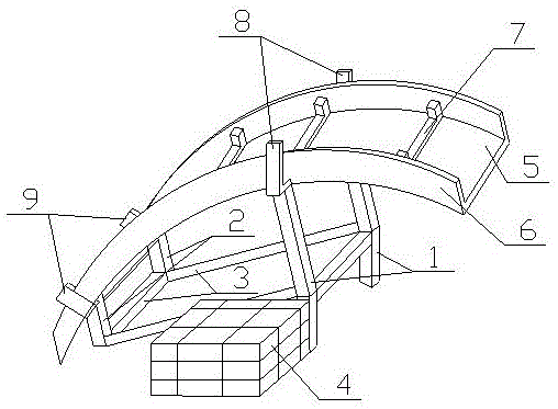
[0002] At present, with the substantial improvement of the quality of urban life, more and more people enter the urban life, and the traffic pressure increases sharply. For this reason, the convenient and fast urban light rail came into being and was favored by the people. For this reason, most The city began to build the subway light rail. Since some road sections need to pass through the ground, the tunnel produced by the shield needs to use steel structure concrete segments to reinforce the tunnel wall. The main reinforcement is welded. The traditional process requires the upper and lower ends of the longitudinal main reinforcement to be clamped with hook reinforcement to enhance the strength of the longitudinal main reinforcement. It needs to be completed on a welding frame. Due to the high hardness of the steel reinforcement, manual engagement is difficult. The traditional bench used for the sheet steel structure skeleton bench is the same height at both ends. It is laborious for the workers to install and weld the transverse main reinforcement (need to bend down), the welding time is longer, and the welding efficiency is lower.

Method used


Image

  • Novel duct piece steel structural framework and welding method thereof
  • Novel duct piece steel structural framework and welding method thereof
  • Novel duct piece steel structural framework and welding method thereof

Examples


Embodiment Construction

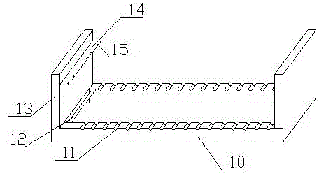
[0030] Such as figure 1 , figure 2 , image 3 , Figure 4 , Figure 5 , Image 6 with Figure 7 Shown: a new segment steel structure skeleton, including: transverse main ribs 22, longitudinal main ribs 23, welding points 24, grouting hole embedded parts 25, fixing hole embedded parts 26, characterized in that: the transverse The main ribs 22 are longitudinally arranged with longitudinal main ribs 23, and there are welding spots 24 at the intersections between each longitudinal main rib 23 and each transverse main rib 22. The skeleton network formed by the plurality of longitudinal main ribs 23 and the plurality of transverse main ribs 22 is There is a grouting hole embedded part 25 at the site, three sets of fixed hole embedded parts 26 are arranged symmetrically in the front and back of the skeleton net, and two sets of fixed hole embedded parts 26 are arranged symmetrically in the left and right sides. The longitudinal main reinforcement 23 includes square main reinfor...


PUM


Abstract

The invention discloses a novel duct piece steel structural framework, comprising horizontal main reinforcements (22), longitudinal main reinforcements (23), welding spots (24), an injected hole embedded part (25), and fixing hole embedded parts (26). The horizontal main reinforcements (22) are longitudinally provided with the longitudinal main reinforcements (23). The intersection of each longitudinal main reinforcement (23) and each horizontal main reinforcement (22) is provided with the welding spot (24). The middle position of a framework net formed by the plurality of longitudinal main reinforcements (23) and the plurality of horizontal main reinforcements (22) is provided with the injected hole embedded part (25). Symmetric positions of the front and the rear of the framework net are provided with three groups of fixing hole embedded parts (26). Symmetric positions of the left and right of the framework net are provided with two groups of fixing hole embedded parts (26). The duct piece steel structural framework is formed by improving a process and changing manual installation of hooked bars into direct welding. In addition, equipment for welding the framework is improved, so as to greatly save installation time of the hooked bars and save labor amount, and improve production efficiency.

Description

technical field [0001] The invention relates to a segment steel structure skeleton, in particular to a novel segment steel structure skeleton and a welding method thereof. Background technique [0002] At present, with the substantial improvement of the quality of urban life, more and more people enter the urban life, and the traffic pressure increases sharply. For this reason, the convenient and fast urban light rail came into being and was favored by the people. For this reason, most The city began to build the subway light rail. Since some road sections need to pass through the ground, the tunnel produced by the shield needs to use steel structure concrete segments to reinforce the tunnel wall. The main reinforcement is welded. The traditional process requires the upper and lower ends of the longitudinal main reinforcement to be clamped with hook reinforcement to enhance the strength of the longitudinal main reinforcement. It needs to be completed on a welding frame. Due ...

Claims


Application Information

Patent Timeline
IPC IPC(8): E21D11/08B23K9/16
CPCB23K9/16B23K2101/24B23K2103/04E21D11/003E21D11/08
Inventor 王海峰成义勇辛学礼
Owner 南通铁建建设构件有限公司
Learn More