
Automatic deviation-adjustment device and deviation-adjustment method for rubber belt at circle forming section of tubular belt conveyor

A tubular belt conveyor technology, which is applied in the field of automatic belt deviation adjustment device in the circular section of the tubular belt conveyor, can solve the problems of time-consuming and labor-intensive effects, waste of manpower and material resources, and low precision, so as to achieve low cost and ensure alignment The effect of high efficiency in operation and deviation adjustment

Pending Publication Date: 2018-10-02
SANMING UNIV
View PDF9 Cites 0 Cited by
  • Summary
  • Abstract
  • Description
  • Claims
  • Application Information

AI Technical Summary

Problems solved by technology

[0003] At present, the deviation adjustment of the belt conveyor belt is basically manual operation, that is, the inclination of the round idler roller is realized by adding or subtracting gaskets. This adjustment method is a passive and extremely low-precision manual adjustment. It is not only time-consuming and labor-intensive, but also has poor effect, and often wastes a lot of manpower and material resources

Method used


Image

  • Automatic deviation-adjustment device and deviation-adjustment method for rubber belt at circle forming section of tubular belt conveyor
  • Automatic deviation-adjustment device and deviation-adjustment method for rubber belt at circle forming section of tubular belt conveyor
  • Automatic deviation-adjustment device and deviation-adjustment method for rubber belt at circle forming section of tubular belt conveyor

Examples


Embodiment 1

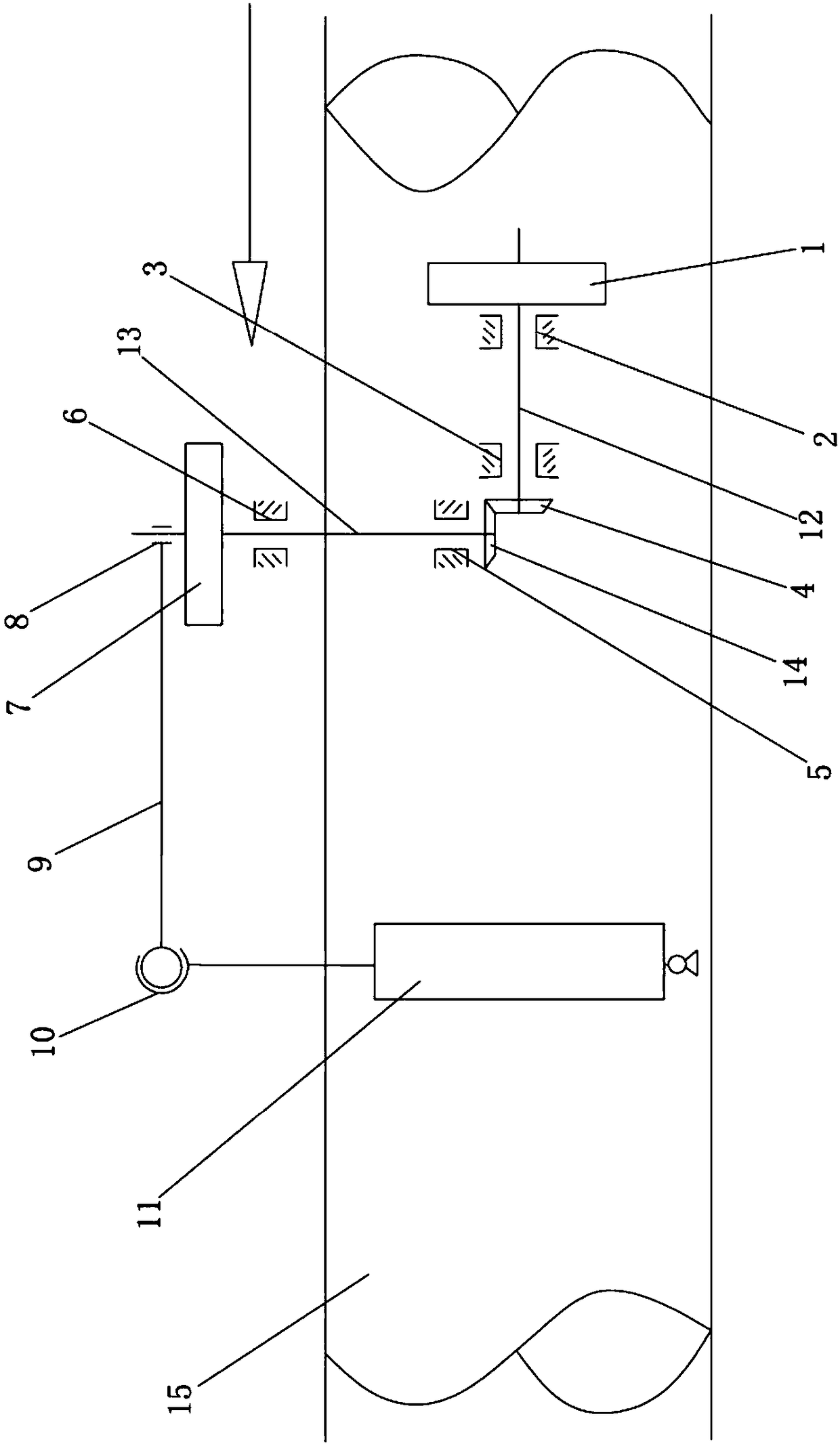
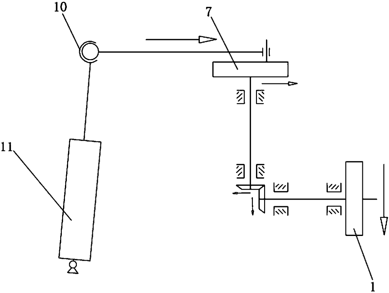
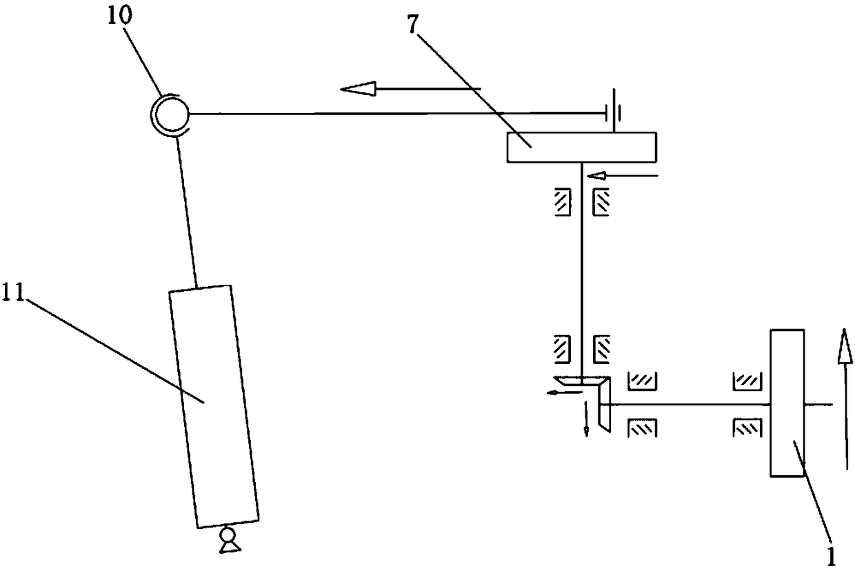
[0019] The automatic deviation adjustment device for the round section of the tubular belt conveyor, such as figure 1 As shown, it includes a transverse transmission mechanism, a longitudinal transmission mechanism, and an idler roller 11. The transverse transmission mechanism includes a first transverse bearing 2 and a second transverse bearing 3 arranged at intervals, and the longitudinal transmission mechanism includes first and second transverse bearings arranged at intervals. Longitudinal bearing 5, second longitudinal bearing 6, described first transverse bearing 2, second transverse bearing 3, first longitudinal bearing 5, second longitudinal bearing 6 are all connected with frame by bearing block; A horizontal rotating shaft 12 is connected between the bearing 2 and the second lateral bearing 3, and the left and right ends of the horizontal rotating shaft 12 extend to the outside of the first lateral bearing 2 and the second lateral bearing 3; the left end of the horizo...


PUM


Abstract

The invention discloses an automatic deviation-adjustment device and a deviation-adjustment method for a rubber belt at a circle forming section of a tubular belt conveyor. The automatic deviation-adjustment device comprises a carrier roller, a first horizontal bearing, a second horizontal bearing, a first longitudinal bearing and a second longitudinal bearing. A horizontal rotary shaft is connected between the first horizontal bearing and the second horizontal bearing; a driving bevel gear wheel and a driving circular disc are connected to the left end and the right end of the horizontal rotary shaft; a longitudinal rotary shaft is connected between the first longitudinal bearing and the second longitudinal bearing; a driven circular disc and a driven bevel gear wheel are connected to theupper end and the lower end of the longitudinal rotary shaft; the driven bevel gear wheel meshes with the driving bevel gear wheel; the carrier roller is connected with a connecting rod through a spherical pair; the connecting rod is eccentrically arranged on the driven circular disc; and when the circle forming section of the rubber belt deviates toward one side, the deviation of the circle forming section of the rubber belt promotes the rotation of the driving circular disc, and the carrier roller automatically produces a corresponding inclination angle through the device, so that the deviated circle forming section of the rubber belt is automatically adjusted. The automatic deviation-adjustment device provided by the invention is ingenious in structure, low in cost, low in failure rate, time and labor saving, and high in deviation-adjustment efficiency.

Description

technical field [0001] The invention relates to an automatic deflection adjustment device and a deflection adjustment method for a round section of a tubular belt conveyor. Background technique [0002] When the belt deviation of the ordinary belt conveyor is serious, the conveyor belt will fall off the idler roller, causing a major accident in the operation of the belt conveyor; , and the phenomenon of deviation to one side; therefore, special attention should be paid to the running state of the belt during installation, adjustment, operation and maintenance to prevent accidents caused by belt deviation; at present, the specific adjustment method for belt deviation of ordinary belt conveyors is: belt deviation Which side, the side of the grooved idler group moves forward toward the forward direction of the belt conveyor, or the other side moves backward, so that the idler produces a correction angle; The forces will no longer be equal and the belt position will be correcte...

Claims


Application Information

Patent Timeline
Patent Type & Authority Applications(China)
IPC IPC(8): B65G15/64
CPCB65G15/64
Inventor 艾子健张志林曾宇刘文宇
Owner SANMING UNIV
Learn More