Connection apparatus

a technology of connecting apparatus and connecting rod, which is applied in the direction of pulse technique, electronic switching, semiconductor devices, etc., can solve the problems of low “on” resistance, low power dissipation, and low resistan

Active Publication Date: 2012-12-13
ANALOG DEVICES INC
View PDF8 Cites 12 Cited by
  • Summary
  • Abstract
  • Description
  • Claims
  • Application Information

AI Technical Summary

Benefits of technology

[0006]It is thus possible to provide an improved “hot swap” arrangement in which one current control device is selected primarily on its ability to withstand the demands placed on it during a switch on period in which the current in the load and the voltage across the load are evolving, and generally the voltage across the load is building. The second current control device is selected for its properties to behave like a switch. That is to present a very low “on” resistance, thereby minimising the voltage dropped across the second electrically controllable device when it is on, and hence also giving rise to low power dissipation.

Problems solved by technology

That is to present a very low “on” resistance, thereby minimising the voltage dropped across the second electrically controllable device when it is on, and hence also giving rise to low power dissipation.

Method used


Image

  • Connection apparatus
  • Connection apparatus
  • Connection apparatus

Examples


Embodiment Construction

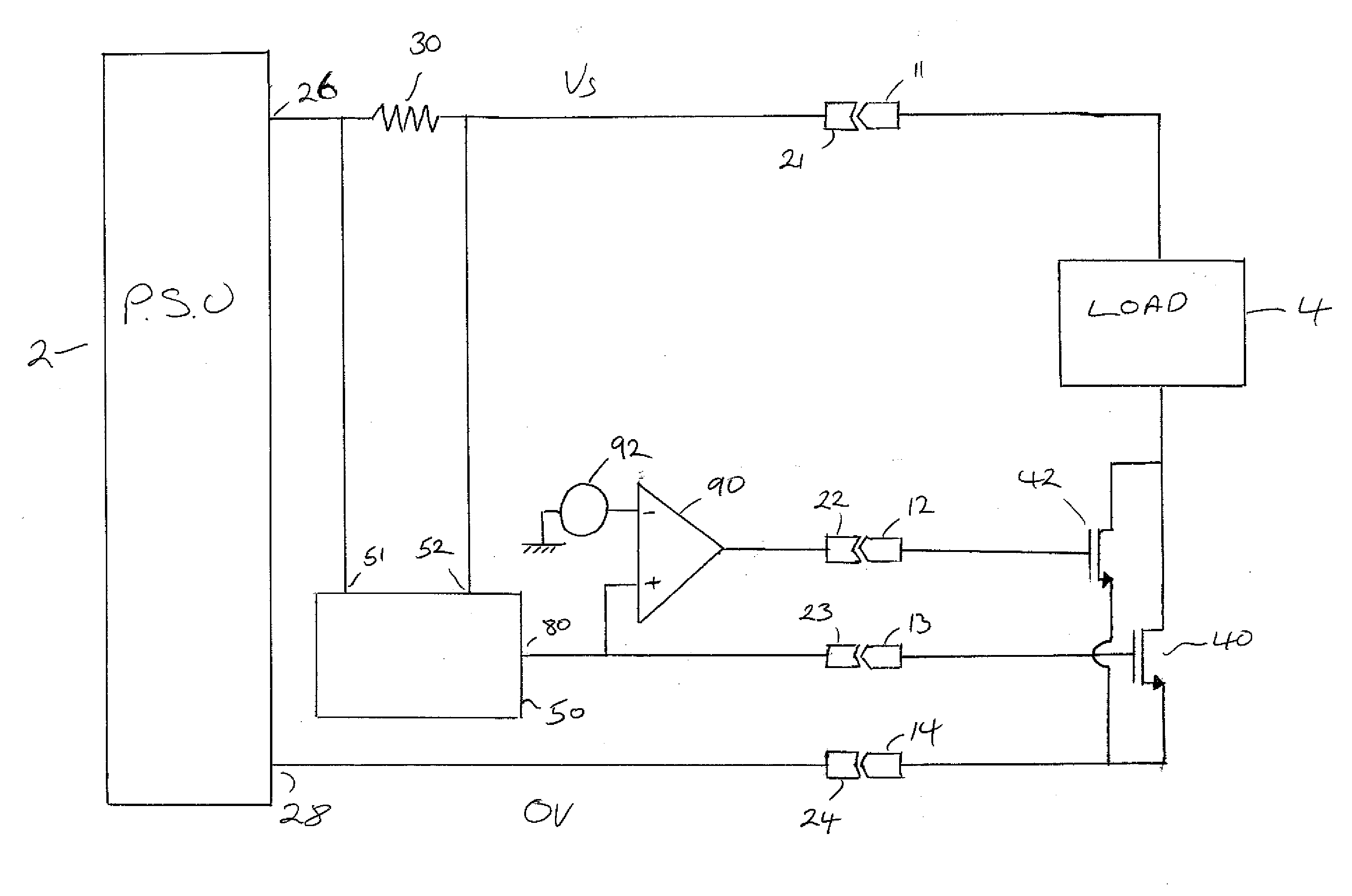
[0036]FIG. 1 schematically illustrates a connection apparatus for controlling inrush currents from a power supply 2 to a load 4 when the load is introduced to the power supply 2 and the power supply 2 is already on and has established its output voltage.

[0037]The power supply 2 may, for example, be serving several other loads which may share a common supply line. Examples of such loads might include computer servers in a rack mounted array or other hot swappable circuit boards. However, on smaller scales the present invention can be applied to any device that is likely to be introduced to an established power supply, such as universal serial bus devices.

[0038]The load 4 can be electrically connected to and disconnected from the power supply 2 by way of a plurality of plugs 11, 12, 13 and 14 cooperating with respective sockets 21, 22, 23 and 24.

[0039]In the arrangement shown in FIG. 1, plug 11 cooperates with socket 21 to establish a connection between a first output 26, such as a po...


PUM


Abstract

A connection apparatus for controlling the supply of electrical power to a load, the connection apparatus comprising first and second electrically controllable devices connected in parallel to each other and in series with the load; wherein the first and second electrically controllable devices are dissimilar, and where a safe operating area product of voltage, current and safe operating area time for the first device is greater than the product of voltage, current and the same safe operating area time for the second device, and an on state resistance for the second device is less than an on state resistance for the first device, and where a controller is provided to use the first device for a first period of time to power up the load, and thereafter the second device is used to maintain power to the load.

Description

FIELD OF THE INVENTION[0001]The present invention relates to a connection apparatus for selectively making an electrical connection between a load and a power supply.BACKGROUND OF THE INVENTION[0002]There are instances when it is desired to connect an electrical load to a power supply that is already on. This can give rise to large inrush currents as capacitive components of the load charge up.[0003]Such inrush currents can perturb the operation of the power supply, possibly causing protective measures within the power supply to trip. Furthermore the inrush currents may introduce perturbations in the power supplied to other loads connected to the power supply, and these perturbations may effect the operation of those circuits.[0004]In order to address these issues it is known to provide “hot swap” circuits that regulate the current flow to a load that is newly introduced to a power supply.SUMMARY OF THE INVENTION[0005]According to a first aspect of the present invention there is pro...

Claims


Application Information

Patent Timeline
Patent Type & Authority Applications(United States)
IPC IPC(8): H03K17/12
CPCH03K17/122H03K17/0822
Inventor TOGNERI, ALDOO'SULLIVAN, MARCUS DANIEL
Owner ANALOG DEVICES INC
Why Eureka
Try Eureka