Unlock instant, AI-driven research and patent intelligence for your innovation.
Optical element, light source device, and projection display device
Active Publication Date: 2012-12-13
NEC CORP
View PDF5 Cites 13 Cited by
Summary
Abstract
Description
Claims
Application Information
AI Technical Summary
This helps you quickly interpret patents by identifying the three key elements:
Problems solved by technology
Method used
Benefits of technology
Benefits of technology
[0012]The present invention can provide an optical element capable of converting randomly polarized light from
Problems solved by technology
Thus, the light passing through the above polarization separation film expands in two dimensions, resulting in increased etendue, and accordingly, improving the use efficiency of light cannot be realized
Method used
Image
Click on the blue label to locate the original text in one second.
Reading with bidirectional positioning of images and text.
Examples
first embodiment
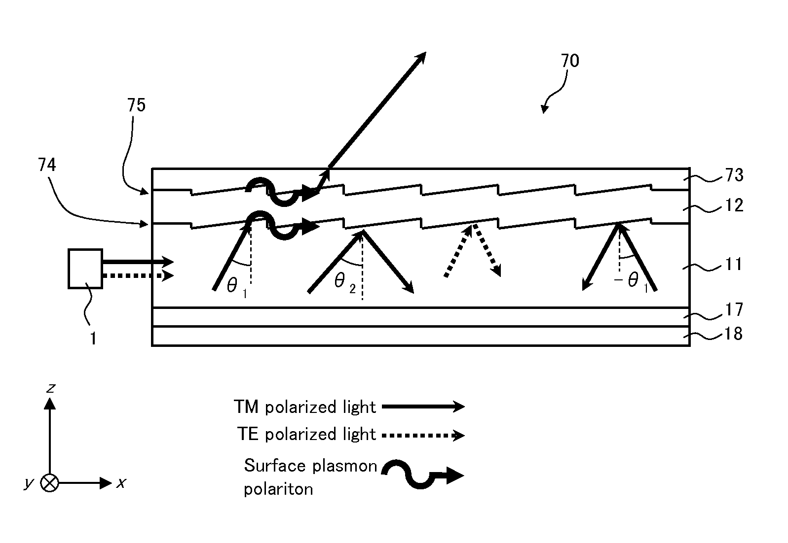
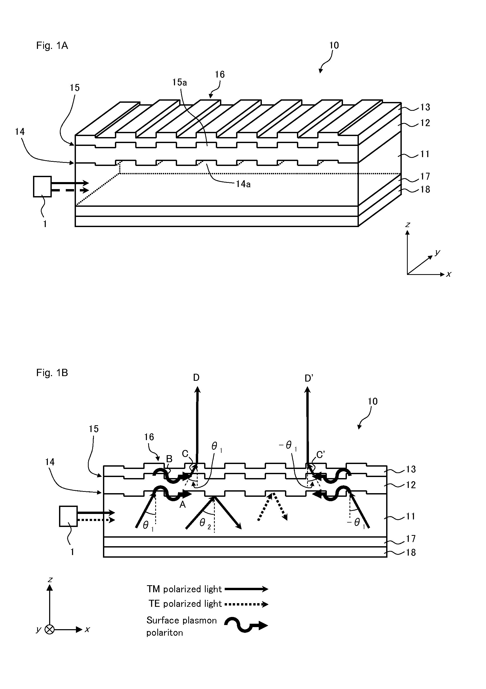
[0031]FIGS. 1A and 1B schematically illustrate an optical element according to a first embodiment. FIG. 1A is a perspective view schematically illustrating the optical element according to this embodiment. FIG. 1B is a cross-sectional view schematically illustrating the optical element according to this embodiment, and shows a cross section taken along a propagation plane in which light propagates within a light guide body accompanied by multiple reflection. In the following description, as shown in FIGS. 1A and 1B, assume that a plane parallel to an upper surface of the light guide body, i.e. an exit surface of the optical element that outputs light is an xy plane, and assume that a direction orthogonal to the exit surface is a z direction. Similarly, assume that an entrance surface is a zx plane, assume that linearly polarized light having a polarization direction parallel to a y direction is a TE polarized light, and assume that a linearly polarized light having a polarization di...
second embodiment
[0067]FIG. 5 is a perspective view schematically illustrating an optical element according to a second embodiment.
[0068]Optical element 20 according to this embodiment is a modification to optical element 10 according to the first embodiment in which a configuration of a light generation means is modified. The light generation means functions similarly to the first embodiment, but differs from the first embodiment in that the light generation means includes metal layer 22, cover layer 23, and low refractive index layer 29 inserted in the interface between them. In other words, in this embodiment, instead of second diffraction grating 15 according to the first embodiment, low refractive index layer 29 having a refractive index lower than that of cover layer 23 is provided in the interface between metal layer 22 and cover layer 23. Except for the above configuration, this embodiment is configured similarly to the first embodiment. In each of the embodiments described below, including ...
third embodiment
[0070]FIG. 6 is a perspective view schematically illustrating an optical element according to a third embodiment.
[0071]This embodiment, similarly to the second embodiment, is a modification to the first embodiment in which a configuration of a light generation means is modified, and differs in that metal layer 32 and cover layer 33 are configured differently from the above embodiments.
[0072]In optical element 30 according to this embodiment, cover layer 33 has a refractive index smaller than that of light guide body 11, and metal layer 32 has a film thickness extremely smaller than that of cover layer 33. The light generation means thus configured, which includes metal layer 32 and cover layer 33, has a so-called “Kretschmann optical configuration”, and utilizes, similarly to the second embodiment, the ATR method to generate light from surface plasmon. Specifically, light is generated from surface plasmon that combines with surface plasmon in first diffraction grating 14 to be induc...
PUM
Abstract
Optical element 10 according to the present invention comprises light guide body 11, surface plasmon excitation means 14 that is provided on the interface with light guide body 11 and that allows surface plasmon to be excited by a specific polarization component of light whose polarization direction is orthogonal to the first direction y in the surface of light guide body 11, from among light entering from light guide body 11, and a light generation means that includes metal layer 12 and cover layer 13, and that generates light having the same polarization component as the specific polarization component of light, from surface plasmon produced in the interface between metal layer 12 and cover layer 13 in response to surface plasmon excited by the specific polarization component in surface plasmon excitation means 14. Surface plasmon excitation means 14 includes a plurality of protrusions 14a, each of which extends in the first direction y and is periodically arrayed along the second direction x orthogonal to the first direction y.
Description
TECHNICAL FIELD[0001]The present invention relates to an optical element utilizing surface plasmon, a light source device and a projection display device.BACKGROUND ART[0002]Recently, a projection display device (LED projector) has been proposed using a light emitting diode (LED) as a light emitting element for a light source.[0003]An LED projector requires an image display with high brightness, and for this purpose it is essential that etendue determined by the light emitting area and the angle of divergence of the light source not be increased. That is, to utilize light from a light source as projection light, it is necessary for the product of the light emitting area and the angle of divergence of the light source to be smaller than the product of the area of the display element and the acceptance angle (solid angle) determined by the F number of the projection lens. In an optical system where light is projected to a light modulation element, it is accordingly necessary to improv...
Claims
Application Information
Patent Timeline
Application Date:The date an application was filed.
Publication Date:The date a patent or application was officially published.
First Publication Date:The earliest publication date of a patent with the same application number.
Issue Date:Publication date of the patent grant document.
PCT Entry Date:The Entry date of PCT National Phase.
Estimated Expiry Date:The statutory expiry date of a patent right according to the Patent Law, and it is the longest term of protection that the patent right can achieve without the termination of the patent right due to other reasons(Term extension factor has been taken into account ).
Invalid Date:Actual expiry date is based on effective date or publication date of legal transaction data of invalid patent.
