Locking pliers

a technology of locking pliers and pliers, which is applied in the field of locking pliers, can solve problems such as adversely affecting the gripping force of workpieces, and achieve the effect of firm and stable gripping for

Active Publication Date: 2013-01-17
WU MING CHIEH
View PDF3 Cites 17 Cited by
  • Summary
  • Abstract
  • Description
  • Claims
  • Application Information

AI Technical Summary

Benefits of technology

[0007]An object of the present invention is to provide a locking pliers which can exert a firm and stable gripping forc...

Problems solved by technology

However, since the first pivot pin 13 is moved to a rear end of the aperture 111 when the jaws 12, 14 are operated to the closed, locked position, the slidi...

Method used


Image

  • Locking pliers
  • Locking pliers
  • Locking pliers

Examples


Embodiment Construction

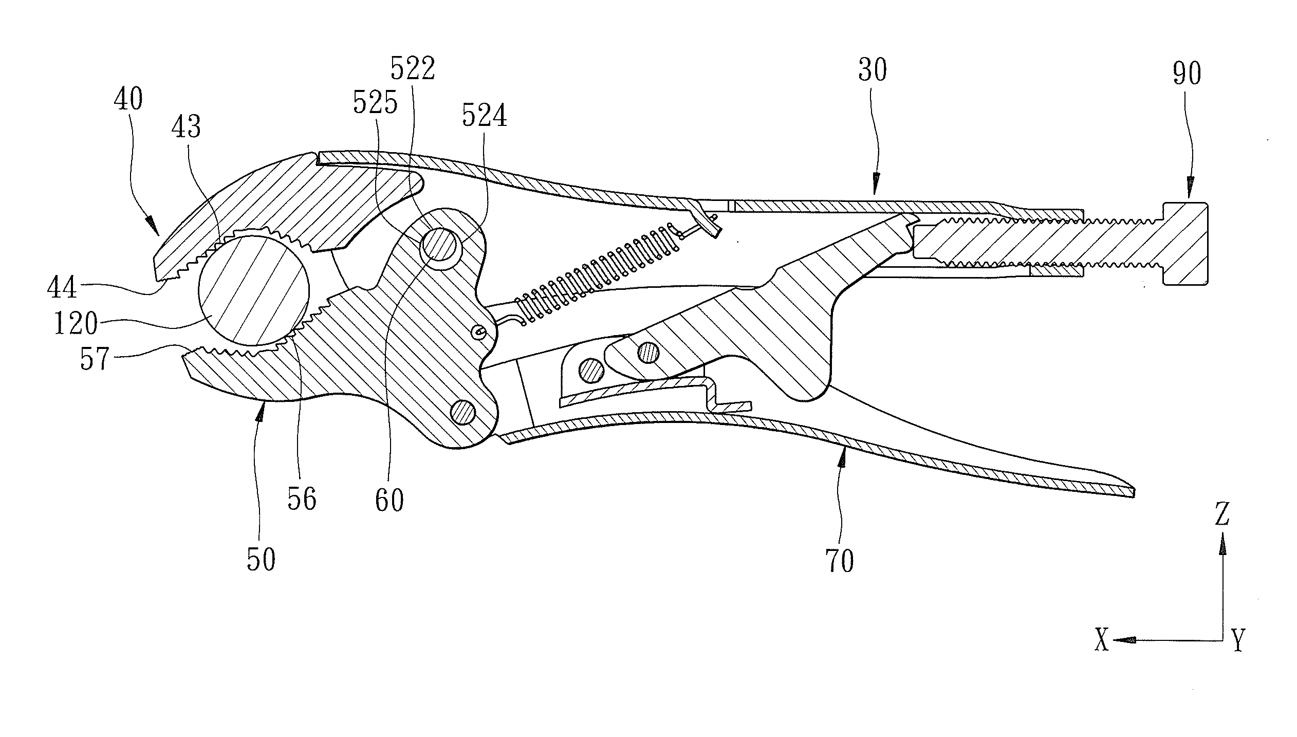
[0022]Referring to FIGS. 4 and 5, the preferred embodiment of a locking pliers according to the present invention is shown to comprise a fixed handle 30, a fixed jaw 40, a movable jaw 50, a movable handle 70, a movable pivot unit, a biasing member 95, and a lock unit 90.

[0023]The fixed handle 30 has front and rear handle portions 31, 32 opposite to each other in a longitudinal direction (X). A pivot hole 33 and a screw hole 34 are formed in the front handle portion 31 and the rear handle portion 32, respectively. In this embodiment, the front handle portion 31 is in the form of a grooved plate which includes an upper plate 311 and a pair of side plates 312 extending from the upper plate 311 in a transverse direction (Z) transverse to the longitudinal direction (X) to cooperatively define a recess 313. The pivot and screw holes 33, 34 are communicated with the recess 313. A tab 314 extends from the upper plate 311 and into the recess 313.

[0024]The fixed jaw 40 has a first connected p...


PUM


Abstract

A locking pliers includes a fixed handle supporting a fixed jaw, a movable jaw, a movable handle pivotally connected to the movable jaw about a pivotal axis, and a movable pivot unit disposed on the fixed handle and the movable jaw. The pivot unit includes a pivot pin and a pivot hole configured to loosely receive the pivot pin such that, when a manual turning force is applied to the movable handle, the movable jaw is turned clockwise to a locking position. As a result of abutting engagement between the pivot pin and a leading region of the pivot hole, a friction force is generated to hold the movable jaw in a tightening position. The gripping force between fixed and movable clamping surfaces of the jaws can be firm and stable.

Description

CROSS-REFERENCE TO RELATED APPLICATION[0001]This application claims priority of Taiwanese Patent Application No. 100124592, filed on Jul. 12, 2011, the disclosure of which is herein incorporated by reference.BACKGROUND OF THE INVENTION[0002]1. Field of the Invention[0003]This invention relates to a locking pliers, more particularly to a locking pliers that can be held firmly in a closed and locked position without the continuous application of force by a user while tightly gripping a workpiece.[0004]2. Description of the Related Art[0005]Referring to FIG. 1, a conventional locking pliers 10 disclosed in U.S. Pat. No. 7,861,622 B2 is shown to include a fixed handle 11 supporting a fixed jaw 12, a movable jaw 14 pivotally connected to the fixed handle 11 by means of a first pivot pin 13, a movable handle 16 pivotally connected to the movable jaw 14 by means of a second pivot pin 15, and a toggle-link locking mechanism 17 disposed to lock the movable jaw in a closed, locked position. T...

Claims


Application Information

Patent Timeline
IPC IPC(8): B25B7/12B25B7/14
CPCB25B7/123
Inventor WU, MING-CHIEH
Owner WU MING CHIEH
Why Eureka
Try Eureka