Eureka AIR delivers breakthrough ideas for toughest innovation challenges, trusted by R&D personnel around the world.

Belt driving device

Active Publication Date: 2013-03-14
SHARP KK
View PDF5 Cites 8 Cited by
  • Summary
  • Abstract
  • Description
  • Claims
  • Application Information

AI Technical Summary

Benefits of technology

The present invention is a mechanism that can correct the meandering of an endless belt in a belt driving device. It uses a deviation transfer member and a biasing member to adjust the tension of the belt and correct the meandering. The mechanism is simple and effective in stabilizing the belt driving process.

Problems solved by technology

Such a belt driving device involves a problem that the endless belt meanders because of variations in the outer diameters of the entraining rollers due to manufacturing errors, parallelism disorders between the entraining rollers due to mounting errors, or the like.
In an image forming apparatus in particular, it is critical to limit the meandering of the endless belt as much as possible because the meandering of the endless belt affects the image quality adversely.
However, such an electric control based technique, however, requires a higher parts count due to the provisions of sensors, electric circuits, driving motor and the like, which raises a problem that the structure becomes complicated while the cost becomes higher.
This might make this technique unable to adjust the tension of the endless belt because increasing frictional force exerted on the belt contact portions with increasing amount of deviation of the endless belt causes the arm member to go beyond the peak and fall down on the downstream side in the running direction of the endless belt by the force of the endless belt running, with the result that the tension imparted by the tension roller to the endless belt becomes extremely weak.
Therefore, it is difficult to correct the meandering of the endless belt stably.

Method used


Image

  • Belt driving device
  • Belt driving device
  • Belt driving device

Examples


Embodiment Construction

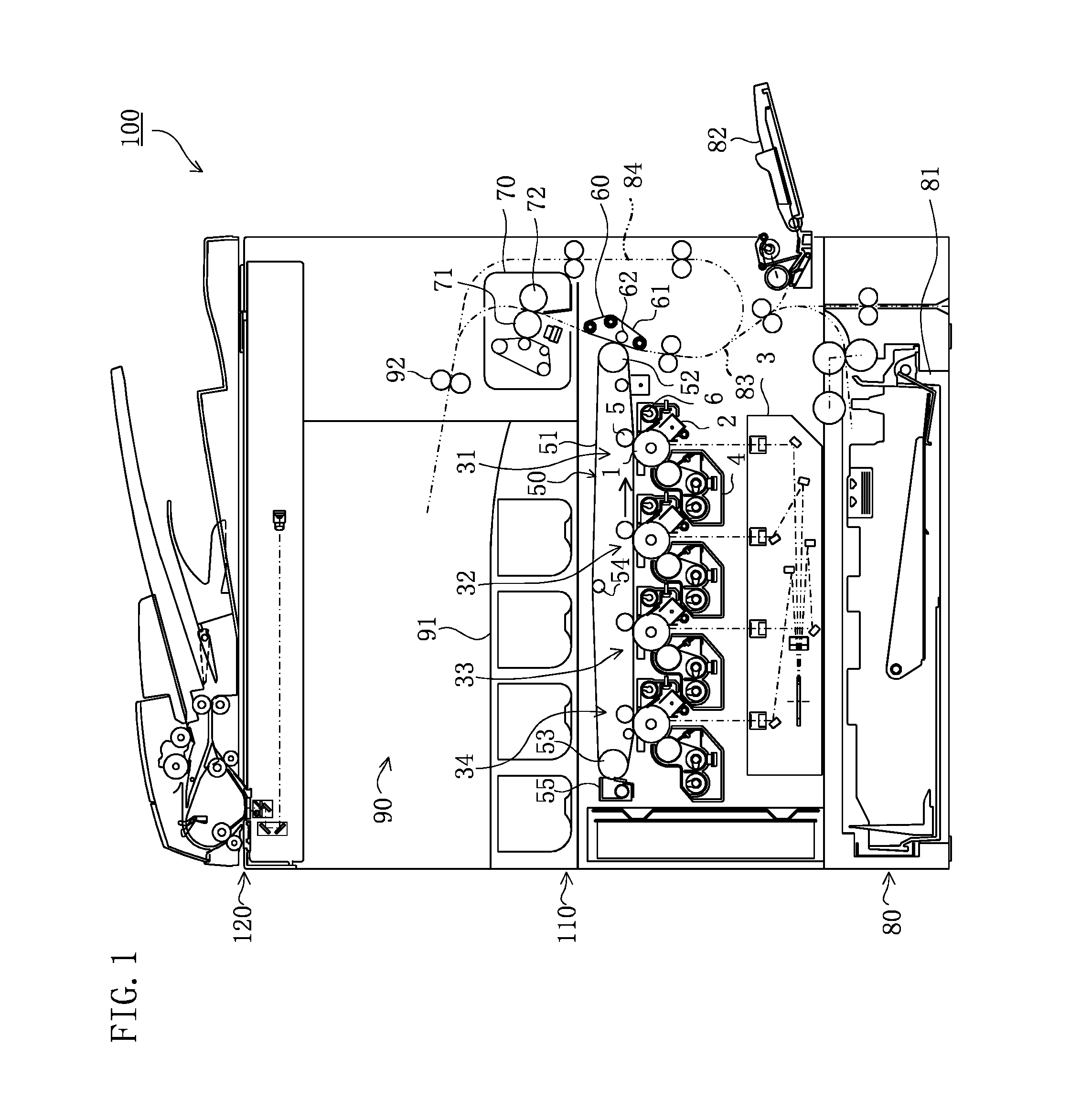
[0020]Hereinafter, embodiments of the present invention will be described with reference to the attached drawings. Referring to FIG. 1, an image forming apparatus 100 is configured to form a monochrome or polychrome image on a recording sheet according to image data created from a document or image data transmitted thereto from the outside. Recording media, such as plain paper, printing paper and OHP film, can be used as the recording sheet.

[0021]The image forming apparatus 100 includes an image reading portion 120, an image forming portion 110, a sheet feeding portion 80, and a sheet output portion 90.

[0022]The image reading portion 120 reads an image from a document to create image data and feeds the image data to the image forming portion 110.

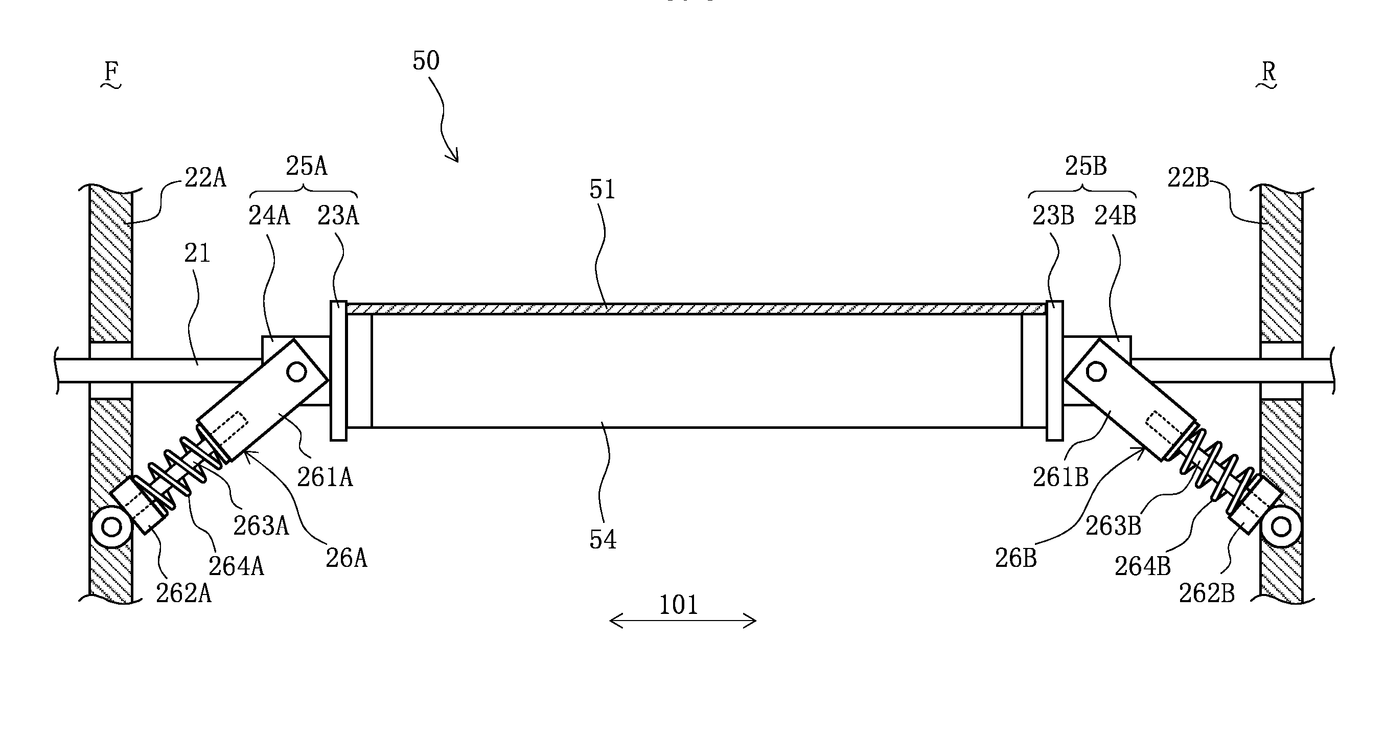
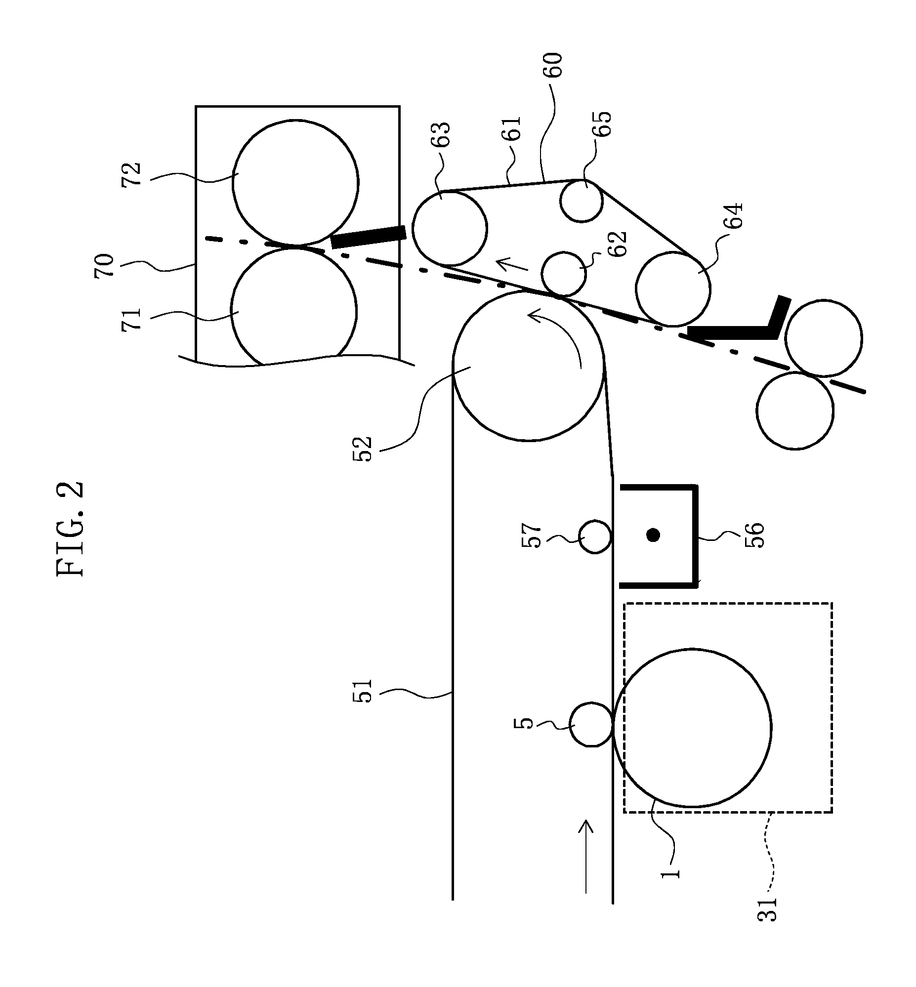
[0023]The image forming portion 110 includes an exposure unit 3, four image forming stations 31 to 34, an intermediate transfer unit 50, a secondary transfer unit 60, and a fixing unit 70. The image forming portion 110 is configured to carry...


PUM


Abstract

A belt driving device includes an endless belt, a tension roller, a shaft member, deviation transfer members, and biasing members. The deviation transfer members are fitted over the shaft member in such a manner as to adjoin respective of opposite ends of the tension roller in an axial direction of the tension roller. Of the deviation transfer members, at least that deviation transfer member which is located on a downstream side in a deviation direction along the axial direction is movable together with the endless belt along the shaft member. Each of the biasing members has an acting end pivotally supported on an associated one of the deviation transfer members and a base end pivotally supported on an associated one of apparatus frames at a predetermined position.

Description

CROSS REFERENCE[0001]This Nonprovisional application claims priority under 35 U.S.C. §119(a) on Patent Application No. 2011-200600 filed in Japan on Sep. 14, 2011 and on Patent Application No. 2011-200601 filed in Japan on Sep. 14, 2011, and the entire contents of which are hereby incorporated by reference.BACKGROUND OF THE INVENTION[0002]The present invention relates to a belt driving device for revolving an endless belt entrained about a plurality of entraining rollers.[0003]Among electrophotographic image forming apparatuses for example, there exists an apparatus of the type which includes an endless belt such as an intermediate transfer belt, a secondary transfer belt, and a fixing belt. One known belt driving device for revolving such an endless belt includes a plurality of entraining rollers positioned parallel with each other for entraining the endless belt thereabout and is configured to revolve the endless belt by actuating a driving roller of the entraining rollers. Such a...

Claims


Application Information

Patent Timeline
IPC IPC(8): G03G15/01G03G15/16
CPCG03G2215/00143G03G15/1615G03G2215/00151
Inventor OKAMOTO, SHOTAROSAKA, MASAKI
Owner SHARP KK
Why Eureka
Eureka Blog
Learn More