Virtual image display device and manufacturing method of virtual image display device

Active Publication Date: 2013-03-21
SEIKO EPSON CORP
View PDF1 Cites 172 Cited by
  • Summary
  • Abstract
  • Description
  • Claims
  • Application Information

AI Technical Summary

Benefits of technology

[0007]An advantage of some aspects of the invention is to provide a virtual image display device having a hard coating layer in which damage may be suppressed a

Problems solved by technology

Accordingly, for example, if cleansing is performed as pre-processing of the deposition of the hard coating layer, the optical e

Method used


Image

  • Virtual image display device and manufacturing method of virtual image display device
  • Virtual image display device and manufacturing method of virtual image display device
  • Virtual image display device and manufacturing method of virtual image display device

Examples


Example

[0038]As below, a virtual image display device according to the first embodiment of the invention will be explained in detail with reference to the drawings.

A. Appearance of Virtual Image Display Device

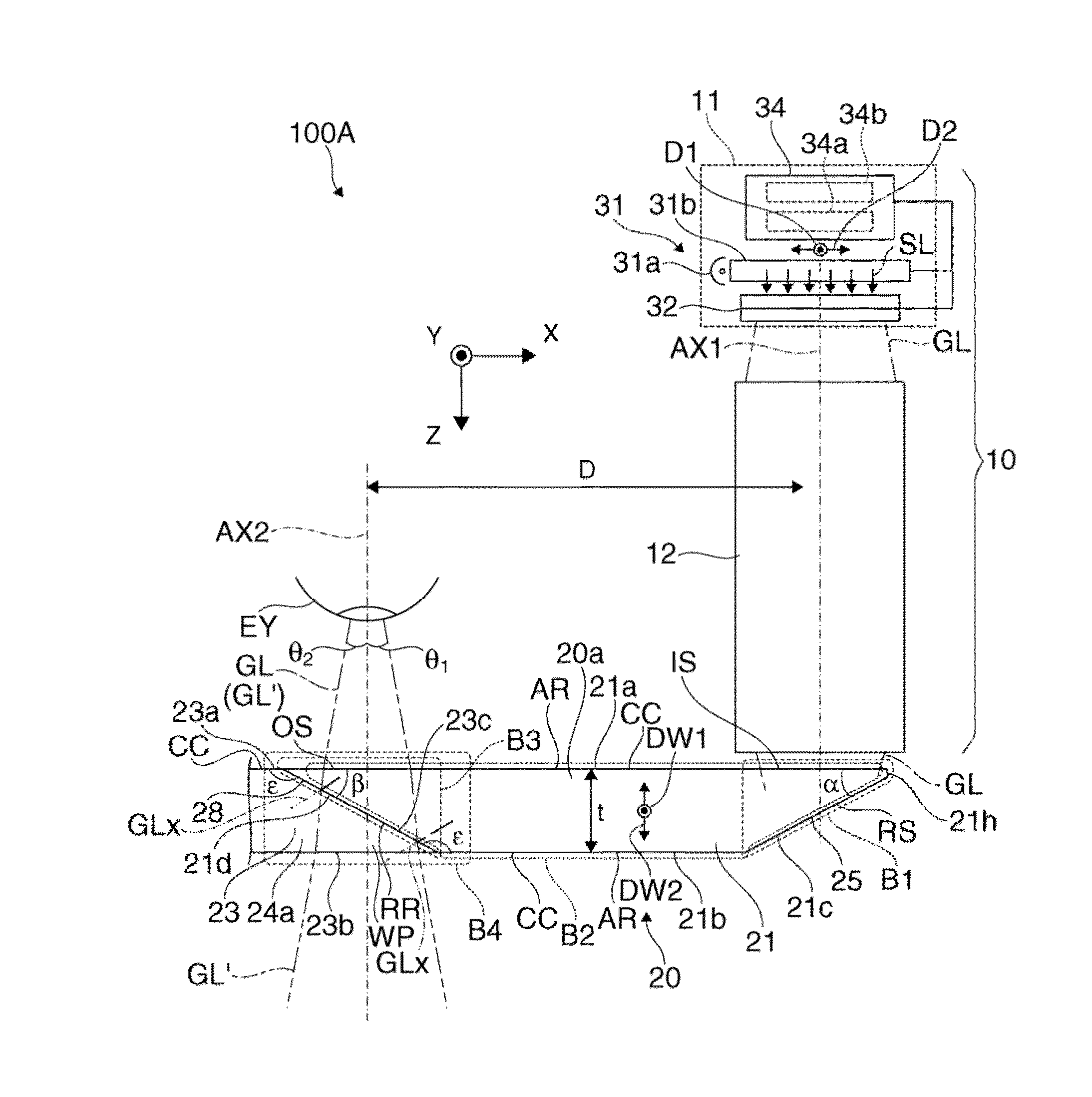
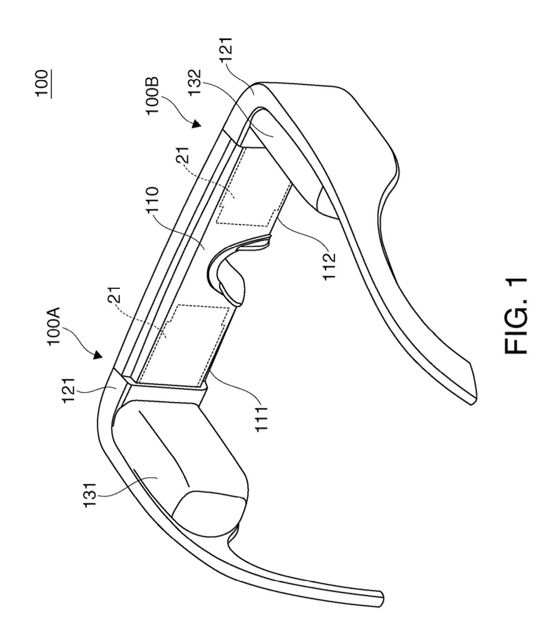
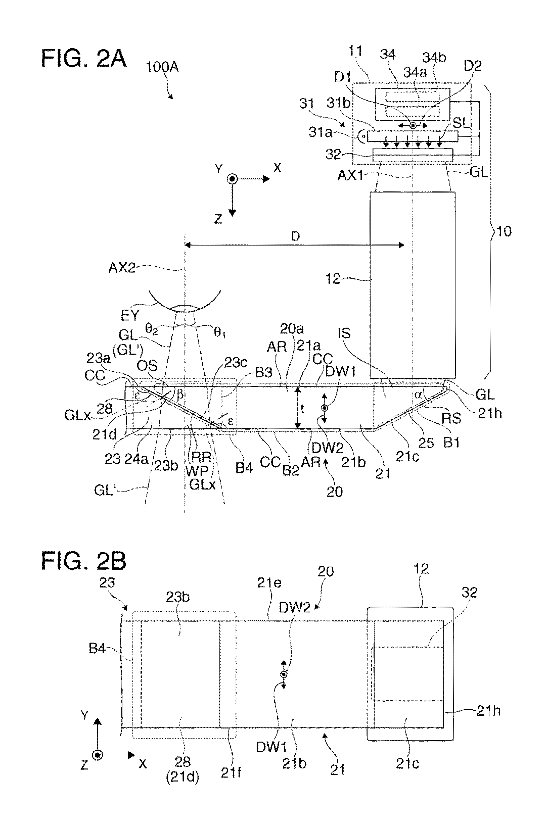
[0039]A virtual image display device 100 of the embodiment shown in FIG. 1 is a head-mounted display having an appearance of eyeglasses, and enables an observer wearing the virtual image display device 100 to recognize image light by a virtual image and observe an external image in a see-through manner. The virtual image display device 100 includes an optical panel 110 that covers the view of observer, a frame 121 that supports the optical panel 110, first and second drive parts 131, 132 added to parts from an end piece to a temple of the frame 121. Here, the optical panel 110 has a first panel part 111 and a second panel part 112, and the panel parts 111, 112 are integrally connected at the center to form a plate-like member. A first display unit 100A formed by combining the first pa...

Example

Second Embodiment

[0082]As below, fabrication steps of a virtual image display device according to the second embodiment using FIGS. 7A to 7F will be explained, and thereby, the virtual image display device of the embodiment will be explained. Note that the virtual image display device 200 of the embodiment is a modified example of the virtual image display device 100 of the first embodiment and the parts or items without particular explanation are the same as those of the first embodiment, and illustration and explanation will be omitted for others than the structure of a light guiding unit 220 forming the virtual image display device 200. FIG. 1A is a sectional view showing the structure of the light guiding unit 220 manufactured through the respective steps, and FIGS. 7B to 7F show the respective steps for fabrication of the structure in FIG. 7A.

[0083]First, as shown in FIG. 7B, the light guide main body part 20a to be a light guide member 221 is prepared. As shown in FIG. 7C, a h...


PUM

PropertyMeasurementUnit
Angleaaaaaaaaaa
Hardnessaaaaaaaaaa

Abstract

In fabrication of a light guiding unit, a half mirror layer as a reflection film for folding light is covered by a light transmission main body part as a coating member, i.e., a light transmission member, and a hard coating layer is deposited thereon. Therefore, even when the surfaces of a light guide main body part and the light transmission main body part forming the light guiding unit are cleansed as pre-processing of the deposition of the hard coating layer, the situations such that the half mirror layer is separated thereby may be avoided and optical properties of the half mirror layer may not be lost.

Description

BACKGROUND[0001]1. Technical Field[0002]The present invention relates to a virtual image display device such as a head-mounted display mounted on a head.[0003]2. Related Art[0004]Recently, as virtual image display devices that enable formation and observation of virtual images like head-mounted displays, various devices of a type of guiding image light from a display element to eyes of an observer using a light guide plate have been proposed (see Patent Document 1 (JP-A-2008-172367) and Patent Document 2 (JP-A-2000-249969)). For example, see-through systems that can superimpose image light and external light by incorporating hologram elements in the light guide plates have been proposed (see Patent Document 3 (JP-A-2007-240924)). Further, not for the head-mounted display, a technology of providing a hard coating layer for protection of surfaces of resin molded components has been generally known (see Patent Document 4 (JP-A-2009-51920)).[0005]In the head-mounted display, in order to...

Claims


Application Information

Patent Timeline
IPC IPC(8): G02B27/01B05D5/06G02B1/10G02B1/14G02B5/08G02B27/02H04N5/64
CPCG02B2027/0178G02B6/0035G02B6/0018G02B27/0172G02B6/00G02B1/14
Inventor TAKEDA, TAKASHITOTANI, TAKAHIROTAKAGI, MASAYUKIKOMATSU, AKIRAMIYAO, TOSHIAKI
Owner SEIKO EPSON CORP
Why Eureka
Try Eureka