Electronic devices

a technology of electronic devices and keys, applied in the direction of electrical apparatus construction details, instruments, casings/cabinets/drawers, etc., can solve the problems of complex preparation operations and difficulty in hearing voices, and achieve the effect of simplifying the operation of keys

Inactive Publication Date: 2013-04-04
SEMICON ENERGY LAB CO LTD
View PDF6 Cites 2 Cited by
  • Summary
  • Abstract
  • Description
  • Claims
  • Application Information

AI Technical Summary

Benefits of technology

[0012]This constitution makes it possible to simplify the operation of the keys. When the electronic device is used as a cellular phone, further, the transmitting unit can be brought close to the mouth, enabling the voice to be clearly transmitted to a remote user.

Problems solved by technology

However, complex operations are necessary for preparing a mail by manipulating the keys provided in the operation unit.
Further, the electronic device makes a communication by using wireless electromagnetic waves, and it often happens that the voice is heard with difficulty depending upon an environment in which the user is placed.

Method used


Image

  • Electronic devices
  • Electronic devices
  • Electronic devices

Examples


embodiment 1

[0042]In the foregoing was described the case where the display device was used for the display unit only. In the electronic device of this embodiment, however, a display device is provided under the operation key 105. FIGS. 6A to 6B are sectional views illustrating the constitution of the operation key 105 under which the light-emitting device is provided.

[0043]In FIG. 6A, a printed board 202 made of a glass epoxy resin or a ceramic material exists inside the housing 201. As a base band unit, there are formed signal processing circuits such as CPU (microprocessor), DSP (digital signal processor) and various memories (flush memory and SRAM) as well as transmitting / receiving circuit unit mounting a mixer and a frequency synthesizer.

[0044]A light-emitting device 204 is provided on the surface of the printed hoard 202 on the side opposite to the surface on where the above various circuits are formed. The light-emitting device 204 includes a substrate 212, a unit display 205 and a cover...

embodiment 2

[0051]FIG. 7 is a block diagram illustrating a system using the electronic device of the invention. In the system shown in FIG. 7, a key input unit 522 includes a display device 523 and a key input detector unit 524. A keyboard interface unit 508 in a CPU 506 controls the picture of symbols displayed by the display device 523 via a keyboard control circuit (controller) 520.

[0052]A signal from the key input detector unit 524 is input to the keyboard interface unit 508 via an input signal processing circuit 521, whereby the data is processed in the CPU 506, a predetermined data is output to the control circuit 512, and the data is displayed on the display device 513 or is transmitted.

[0053]The external circuit is constituted by a power source 504 which includes a stabilized power source and a high-speed and high-precision operational amplifier, a voice processing circuit 502, an external interface port 505, and a transmitting / receiving circuit 515. The CPU 506 contains a video signal ...

embodiment 3

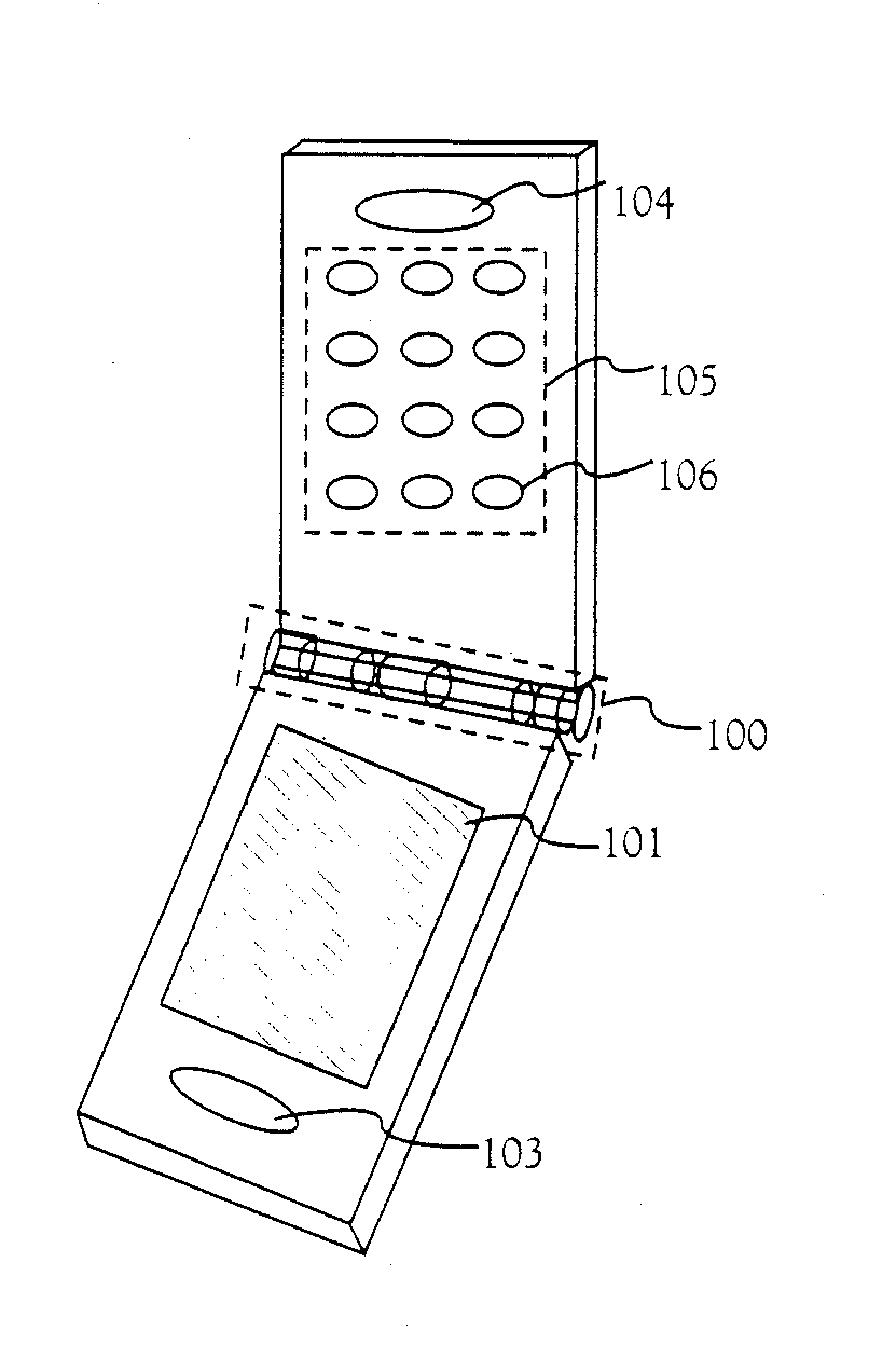
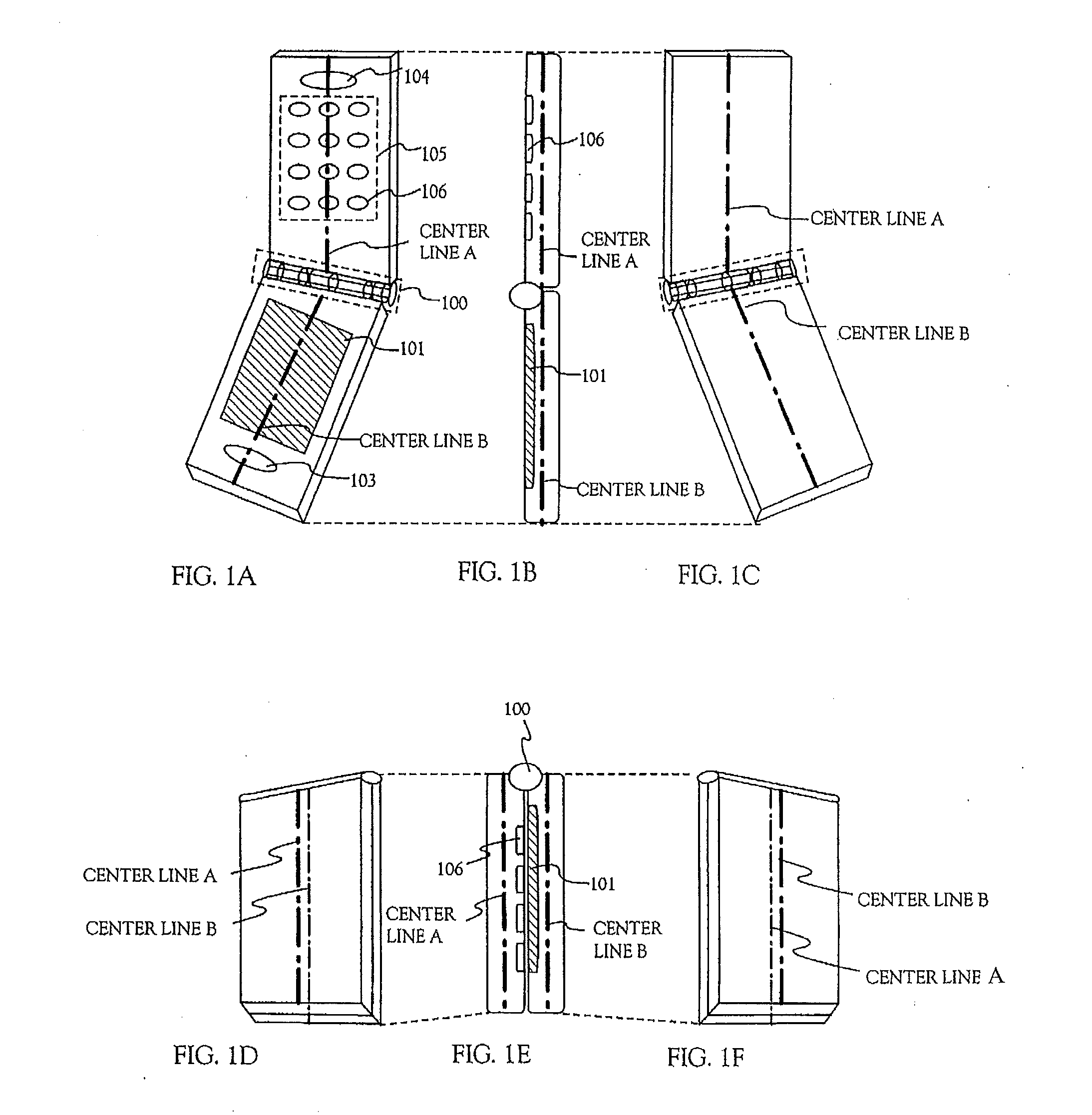
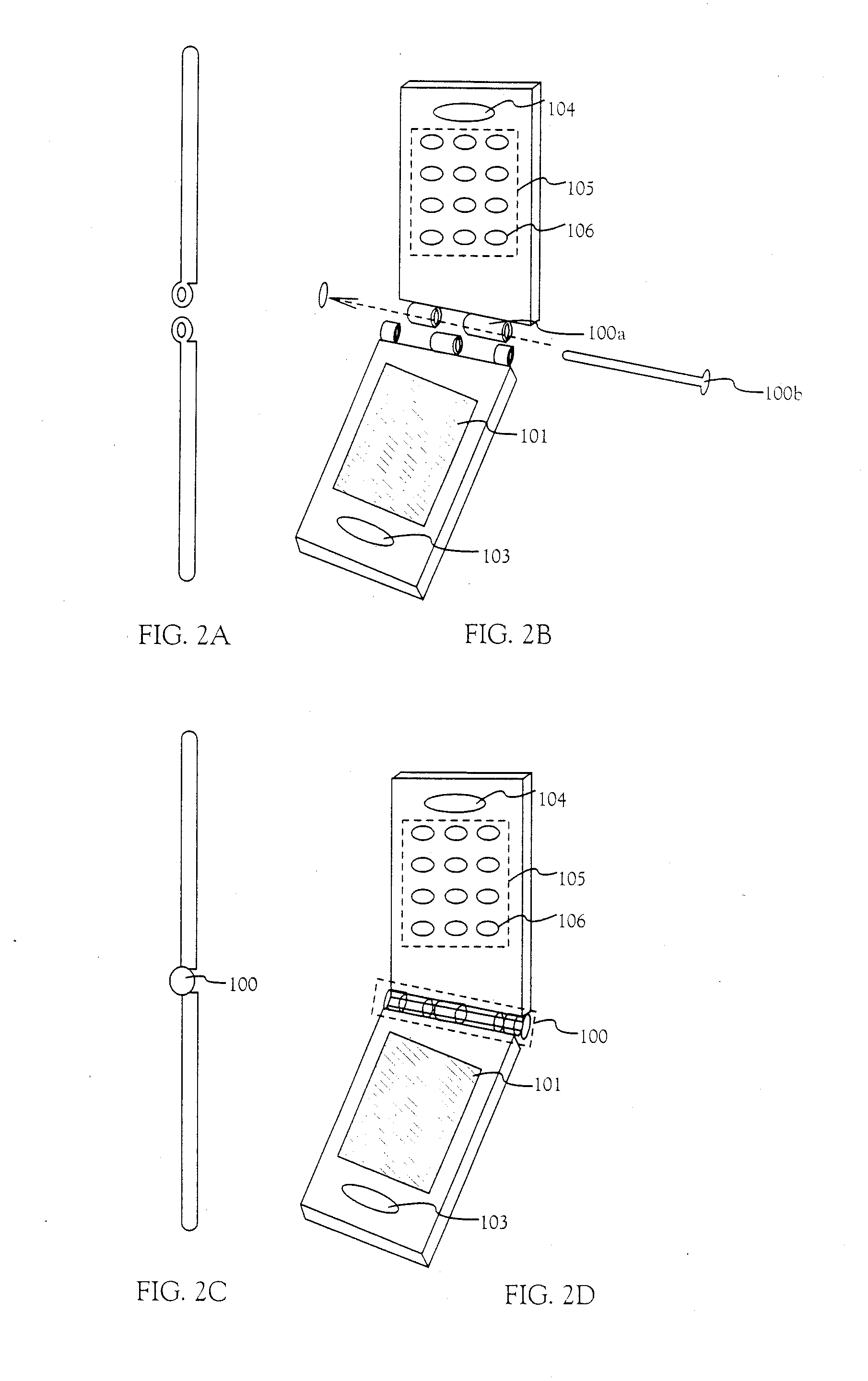
[0056]Next, FIGS. 8A to 8B show the appearance of the electronic device using the display device for the operation key dealt with in the embodiments 1 and 2. FIG. 8A illustrates a case where, when the first housing and the second housing are arranged in the vertical direction, the direction of symbols displayed on the display unit 101 and the direction of symbols displayed on the buttons 106 in the operation key 105, are in what they should be as viewed from the side of the user.

[0057]FIG. 8B illustrates a case where, when the first housing and the second housing are arranged in the lateral direction, the direction of symbols displayed on the display unit 101 and the direction of symbols displayed on the buttons 106 in the operation key 105, are in what they should be as viewed from the side of the user.

[0058]The electronic device of the invention is capable of changing the direction of the symbols displayed on the display unit 101 and the direction of the symbols displayed on the b...


PUM


Abstract

An electronic device capable of transmitting and receiving a mail through an internet usually has from 12 to 20 operation keys inclusive of numerical keys and special keys. In order to input Japanese characters inclusive of “kanji” and special characters as data, complex operations must be executed by changing over the input mode. A portable data terminal as represented by a cellular phone or an electronic device such as a data terminal as represented by a personal computer or a desk top telephone, has such a shape that the first center-line of the first housing and the second center line of the second housing come into agreement and in parallel with each other only in a state where the first housing and the second housing are folded by the hinge.

Description

CROSS-REFERENCE TO RELATED APPLICATIONS[0001]This application is a continuation of U.S. application Ser. No. 10 / 072,496, filed Feb. 5, 2002, now allowed, which claims the benefit of a foreign priority application filed in Japan as Serial No. 2001-030840 on Feb. 7, 2001, both of which are incorporated by reference.BACKGROUND OF THE INVENTION[0002]1. Field of the Invention[0003]This invention relates to electronic devices such as an information terminal, a cellular phone, a PHS (personal handy phone system) and a PDA (personal digital assistant) that are connected to the Internet to transmit and receive data. In this specification, the electronic device stands for those that can be carried by a user, and is capable of transmitting and receiving data and information indoors and outdoors through a wireless phone, a wired phone or an Internet.[0004]2. Description of the Related Art[0005]Electronic devices as represented by a cellular phone (portable phone) are finding a rapid and widespr...

Claims


Application Information

Patent Timeline
Patent Type & Authority Applications(United States)
IPC IPC(8): H05K7/00G06F1/16H04M1/02H04M1/22H04M1/23H04W88/02
CPCH01H2217/048H01H2219/012H01H2221/07H05K7/00H04M1/22H04M1/23H04M1/0216
Inventor YAMAZAKI, SHUNPEIWATANABE, YASUKO
Owner SEMICON ENERGY LAB CO LTD
Why Eureka
Try Eureka