Method and apparatus to measure differntial phase and frequency modulation distortions for audio equipment

a technology of frequency modulation and audio equipment, applied in the field of audio equipment testing, can solve the problems of sideband distortion, quantizing errors can reveal frequency or phase shifts, and still exist discrepancies between the sonic signature of amplifiers and equipmen

Active Publication Date: 2013-07-25
QUAN RONALD
View PDF9 Cites 15 Cited by
  • Summary
  • Abstract
  • Description
  • Claims
  • Application Information

AI Technical Summary

Benefits of technology

[0071]In addition the invention or an embodiment includes a method wherein the test signal includes an optional synchronizing signal, and a method wherein the measured frequency modulation effect is displayed.
[0072]Also included is a method of measuring a phase and or frequency modulation effect of a device, wherein the input of the device is coupled to at least one signal of two or more frequencies, wherein the at least one signal induces a phase or frequency modulation effect on the device, whereby the output of the device is coupled to a tunable filter which tunes to a selected frequency of a signal from the output of the device, and wherein a phase detector and or a frequency modulation detector measures the phase and or frequency modulation effect of the device.
[0073]The invention or an embodiment includes a method of a measuring a phase and or a frequency modulation effect of a device, comprising coupling multiple frequencies to the input of the device, wherein the output of the device generates a frequency modulation effect on one or more of its output si

Problems solved by technology

While these conventional tests are fine for many basic evaluations of the equipment, there still exist discrepancies between the sonic signature of amplifiers and equipment

Method used


Image

  • Method and apparatus to measure differntial phase and frequency modulation distortions for audio equipment
  • Method and apparatus to measure differntial phase and frequency modulation distortions for audio equipment
  • Method and apparatus to measure differntial phase and frequency modulation distortions for audio equipment

Examples


Embodiment Construction

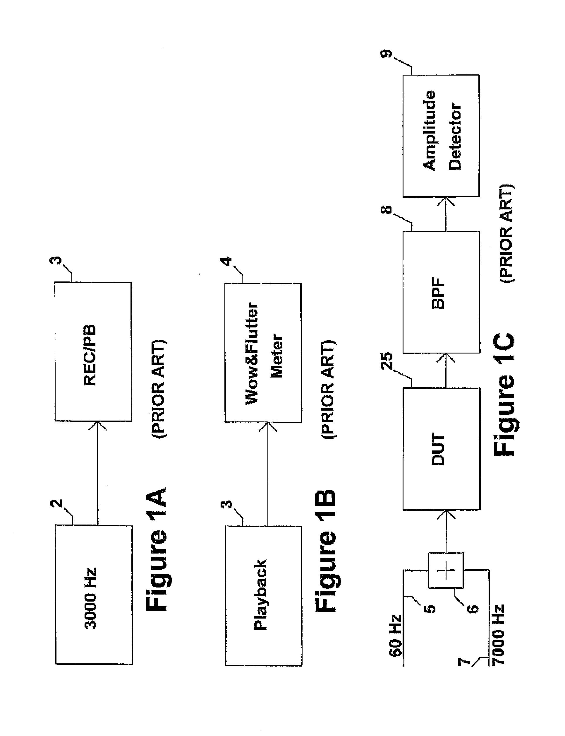
[0105]FIG. 1A shows a standard prior art method of performing a Wow and Flutter test. A test tone signal, 2, of 3000 Hz (or 3150 Hz) tone is coupled to a recorder, 3. This recorder may be a tape recorder or a disc recorder.

[0106]FIG. 1B shows further that the recorded test tone is then played back via 3 and coupled to a Wow and Flutter meter, 4, for measurement of frequency deviations of the singe tone (for a prior art standard method of measuring Wow and Flutter). These frequency deviations of the test tone are for example a result of the non-perfect speed or velocity in which the mechanical recorder exhibits upon recording and or playback.

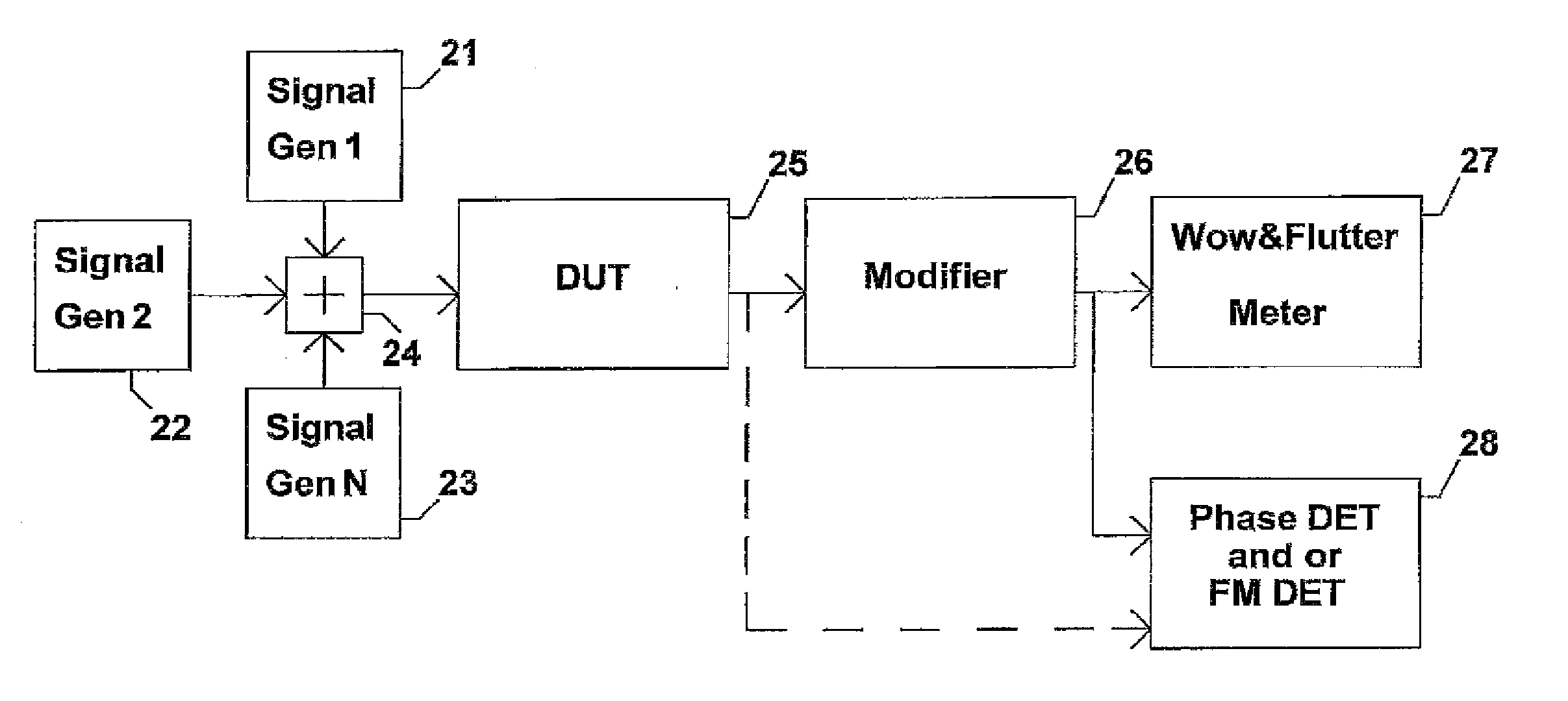
[0107]One object (of the invention) is to assess phase or frequency modulation from an audio system or amplifier caused by the two or more input signals. Therefore, FIG. 1B, which shows standard (prior art) testing for Wow and Flutter, does not apply (for example, to a multiple signal method of an embodiment of the invention) because only one tes...


PUM


Abstract

A testing method or apparatus utilizes multiple frequencies applied to a device under test for measuring newly discovered frequency modulation effects. An embodiment may include a lower frequency signal combined with two (or more) higher frequency signals to test a dynamic change in frequency response, gain, and or phase of the lower frequency signal from an audio device. This dynamic test can reveal frequency modulation effects via the two higher frequency signals emulate a modulated signal that provides a phase or frequency modulation frequency related to the difference of the two higher frequency signals. Another embodiment may include the use of a higher frequency signal and pulsed waveform to dynamically induce a time varying phase or frequency distortion of the pulsed waveform or components of the pulsed waveform from the device that has differential phase distortion. In another embodiment, the device's output is then measured with an FM detector and or phase detector to measure a phase and or frequency shift in one or more signals of the frequencies related to the pulsed waveform, such as a signal of the fundamental frequency and or one or more harmonic related to the pulsed waveform the device.

Description

[0001]This application is a continuation-in-part of U.S. application Ser. No. 12 / 875,563 filed Sep. 3, 2010, which is a continuation-in-part of U.S. application Ser. No. 12 / 707,425 filed Feb. 17, 2010, which is a continuation-in-part of U.S. application Ser. No. 12 / 456,752 filed Jun. 22, 2009, which is a continuation-in-part of U.S. application Ser. No. 11 / 508,700 filed Aug. 23, 2006, which claims benefit of U.S. provisional Ser. No. 60 / 721,027 filed Sep. 27, 2005, which are incorporated herein by reference.BACKGROUND[0002]This invention is related to the testing of audio equipment and, in particular, analog to digital converters (ADC), digital to analog converters (DAC), digital audio processors or recorders, audio amplifiers, and the like.DESCRIPTION OF THE PRIOR ART[0003]Presently, conventional harmonic and or intermodulation distortion tests are used to measure the performance of the audio equipment.[0004]An intermodulation distortion test provides for two tones to be applied to...

Claims


Application Information

Patent Timeline
IPC IPC(8): H04R29/00
CPCH04R29/00G10L25/69G01R31/2825G01R27/28G01R23/20
Inventor QUAN, RONALD
Owner QUAN RONALD
Why Eureka
Try Eureka