Power and communications for remote electronic devices

a technology of electronic devices and communications, applied in the field of power and communications for remote electronic devices, can solve the problems of high voltage required for equipment to function, poor communication, and easy and achieve the effect of avoiding damage to the communication circuitry of the devi

Active Publication Date: 2013-08-15
CAMCON OIL LTD
View PDF4 Cites 1 Cited by
  • Summary
  • Abstract
  • Description
  • Claims
  • Application Information

AI Technical Summary

Benefits of technology

[0012]The device is therefore able to receive power for storage in its power storage arrangement, and receive and / or send communication signals for its communication arrangement via electrical couplings used for both functions. This provides several advantages which are discussed below.
[0014]The device controller may include a sensor for monitoring the voltage across the main device terminals, with the device controller arranged to cause the switching arrangement to disconnect the power input terminals from the main device terminals when the voltage across the main device terminals falls below a predetermined threshold. In this way, the device is able to detect when the power supply phase of operation has ceased and in response disconnect the power input terminals of the device from the main device terminals.
[0015]Preferably, an over-voltage protection arrangement is coupled between the device communication terminals. This avoids damage to the communication circuitry of the device, for example in the loss of synchronisation between the switching arrangement of the device and the associated controller. This may be implemented in the form of a zener diode connected across the device communication terminals for example.

Problems solved by technology

This can be problematic as long lengths of cable are costly and also can have high resistances leading to high voltage drops, meaning that very high voltages may be required for equipment to function.
Communications also suffer due to the resistance of the long wires.
An alternative approach to this is to locally power the device with a battery, but the power output of a battery tends to become impaired due to power leakage and performance decay at high temperatures.
Currently few electrically powered devices are deployed into down-hole environments but the above issues have been addressed in the following ways:1. High voltages are used to overcome the resistance of the cabling so as to give the down-hole device adequate power;2. Systems that are only deployed for a short period of time or only operate for “one shot” are powered by on-board batteries, but these systems may degrade in the higher temperature situations.

Method used


Image

  • Power and communications for remote electronic devices
  • Power and communications for remote electronic devices
  • Power and communications for remote electronic devices

Examples


Embodiment Construction

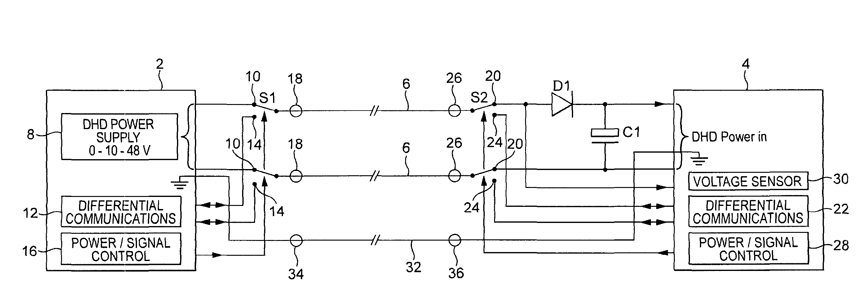
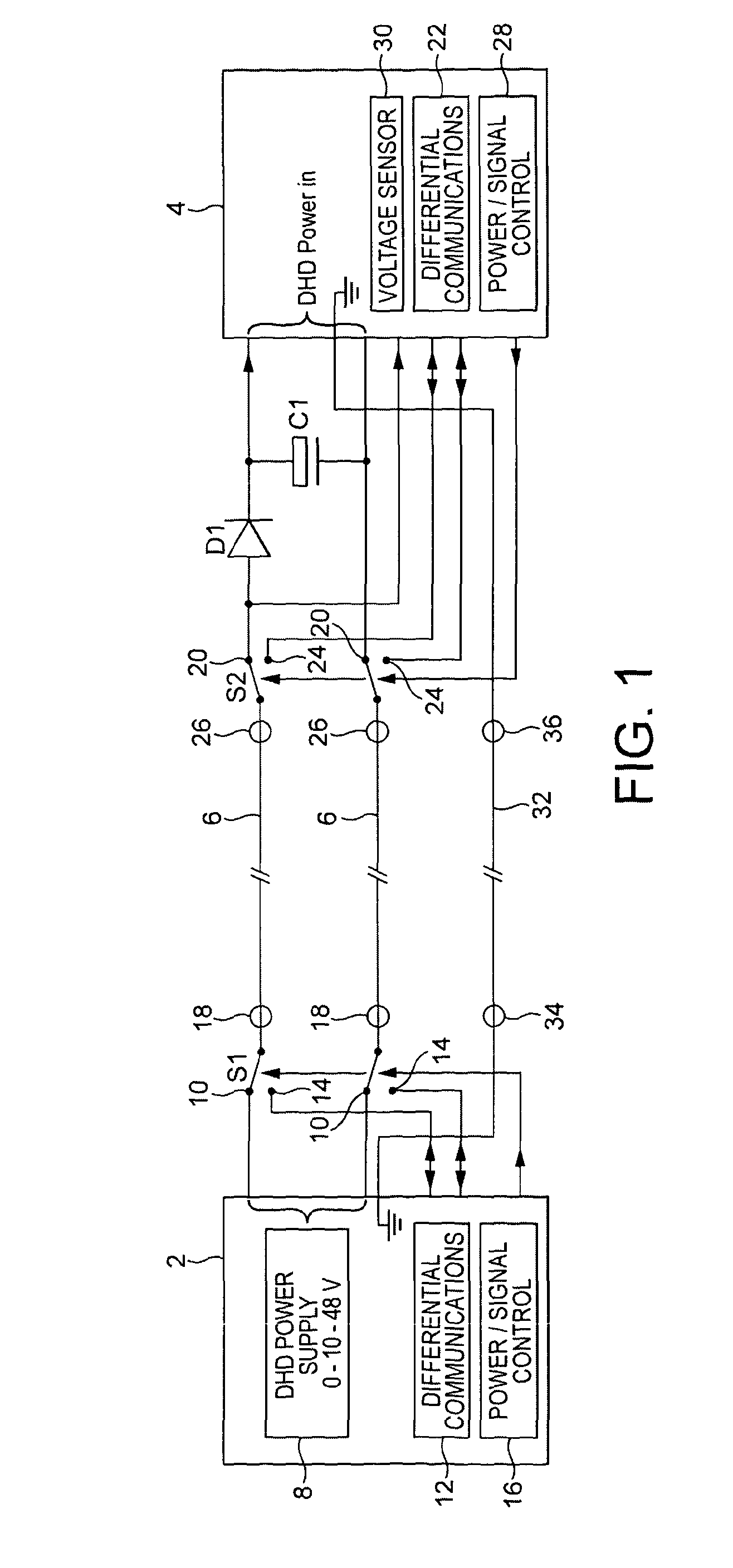
[0042]The invention provides a way of both powering and communicating with an electronic Down Hole Device (referred to as the DHD from here on), which supplies enough energy for the device, whilst potentially using only three wires. This is achieved in the embodiment shown in the Figures by switching between power charging and communication cycles.

[0043]In FIG. 1, a power supply and communication assembly 2 is located above ground and the DHD 4 is suitable for deployment underground, for example down an oil well. Running between these two arrangements is a pair of connectors or wires 6 forming a surface-to-down-hole cable.

[0044]Assembly 2 includes a DHD power supply 8 having two power output terminals 10. It also includes a differential communications arrangement 12 having two associated assembly communication terminals 14. A switch S1 is arranged for selectively coupling either power terminals 10 or communication terminals 14 to wires 6. The operation of switch S1 is governed by a ...


PUM


Abstract

An electronic device (4) for deployment in a remote location such as a well-bore comprises two main device terminals (26) for connection to a remote power supply and communication assembly (2) via two electrical couplings (6); a power storage arrangement (C1) having two power input terminals (20); a device communication arrangement (22) having two device communication terminals (24); a device switching arrangement (S2) for selectively connecting each of the two power input terminals (20) or each of the two device communication terminals (24) to a respective one of the main device terminals (26); and a device controller (28) for controlling the operation of the switching arrangement. A power supply and communication assembly (2) is also provided and arranged to be coupled to one or more of the devices (4).

Description

BACKGROUND[0001]In the oil industry, and other similar industries, there is sometimes a requirement to operate equipment at long distances from any existing source of power. This means that both power and communications each have to be arranged by cable or radio links. This can be problematic as long lengths of cable are costly and also can have high resistances leading to high voltage drops, meaning that very high voltages may be required for equipment to function. Communications also suffer due to the resistance of the long wires.[0002]An alternative approach to this is to locally power the device with a battery, but the power output of a battery tends to become impaired due to power leakage and performance decay at high temperatures.[0003]Currently few electrically powered devices are deployed into down-hole environments but the above issues have been addressed in the following ways:[0004]1. High voltages are used to overcome the resistance of the cabling so as to give the down-h...

Claims


Application Information

Patent Timeline
Patent Type & Authority Applications(United States)
IPC IPC(8): G05B13/02
CPCH04B3/548G05B13/02H04B2203/5475E21B47/12H04L12/10
Inventor HOCKLEY, PHILIP
Owner CAMCON OIL LTD
Why Eureka
Try Eureka