Image reading device and method for manufacturing the same

a reading device and image technology, applied in the direction of film/foil adhesives, paper/cardboard containers, instruments, etc., can solve the problems of long hardening time, efficient assembly, and faster assembly during manufacture, and achieve the effect of assembling more efficiently

Active Publication Date: 2014-04-08
ROHM CO LTD
View PDF19 Cites 0 Cited by
  • Summary
  • Abstract
  • Description
  • Claims
  • Application Information

AI Technical Summary

Benefits of technology

[0008]The present invention is completed through research addressing the aforementioned issues, with the objective of providing an image reading device and a method for manufacturing the same, where the image reading device is capable of being assembled more efficiently.
[0033]According to the manufacturing method, the optical part is fixed in the accommodating portion by using the first adhesive having shorter hardening time before the hardening of the second adhesive. Therefore, when the image reading device is manufactured, it is unnecessary to wait for complete hardening of the second adhesive. Therefore, according to the method for manufacturing the image reading device of the present invention, the delay necessitated by ceasing operation can be reduced, thereby improving manufacturing efficiency.

Problems solved by technology

If silicone resin hardened at a normal temperature is used as the adhesive, it takes a long time to harden.
Another issue with the image reading device X is that faster assembly is required during manufacture.
The time required fixing the linear light source 92 and the lens array 93 to harden the silicone resin hinders efficient assembly.

Method used


Image

  • Image reading device and method for manufacturing the same
  • Image reading device and method for manufacturing the same
  • Image reading device and method for manufacturing the same

Examples


second embodiment

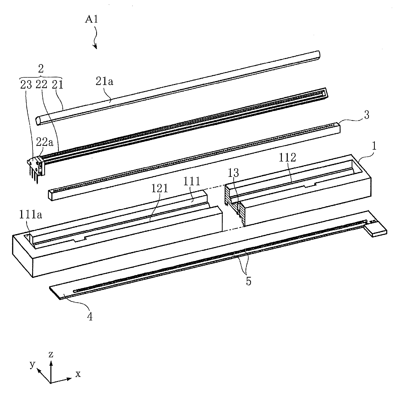
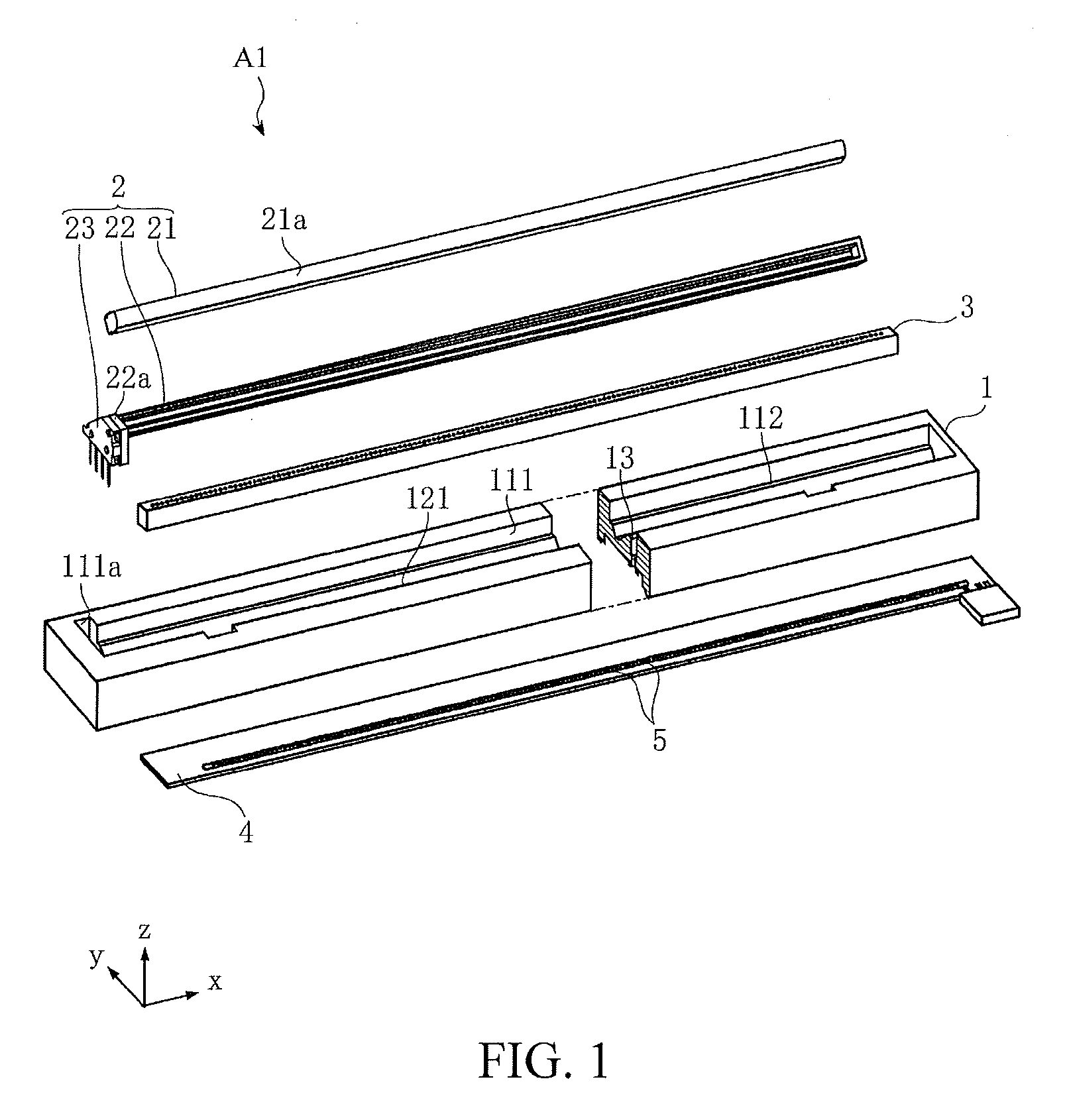
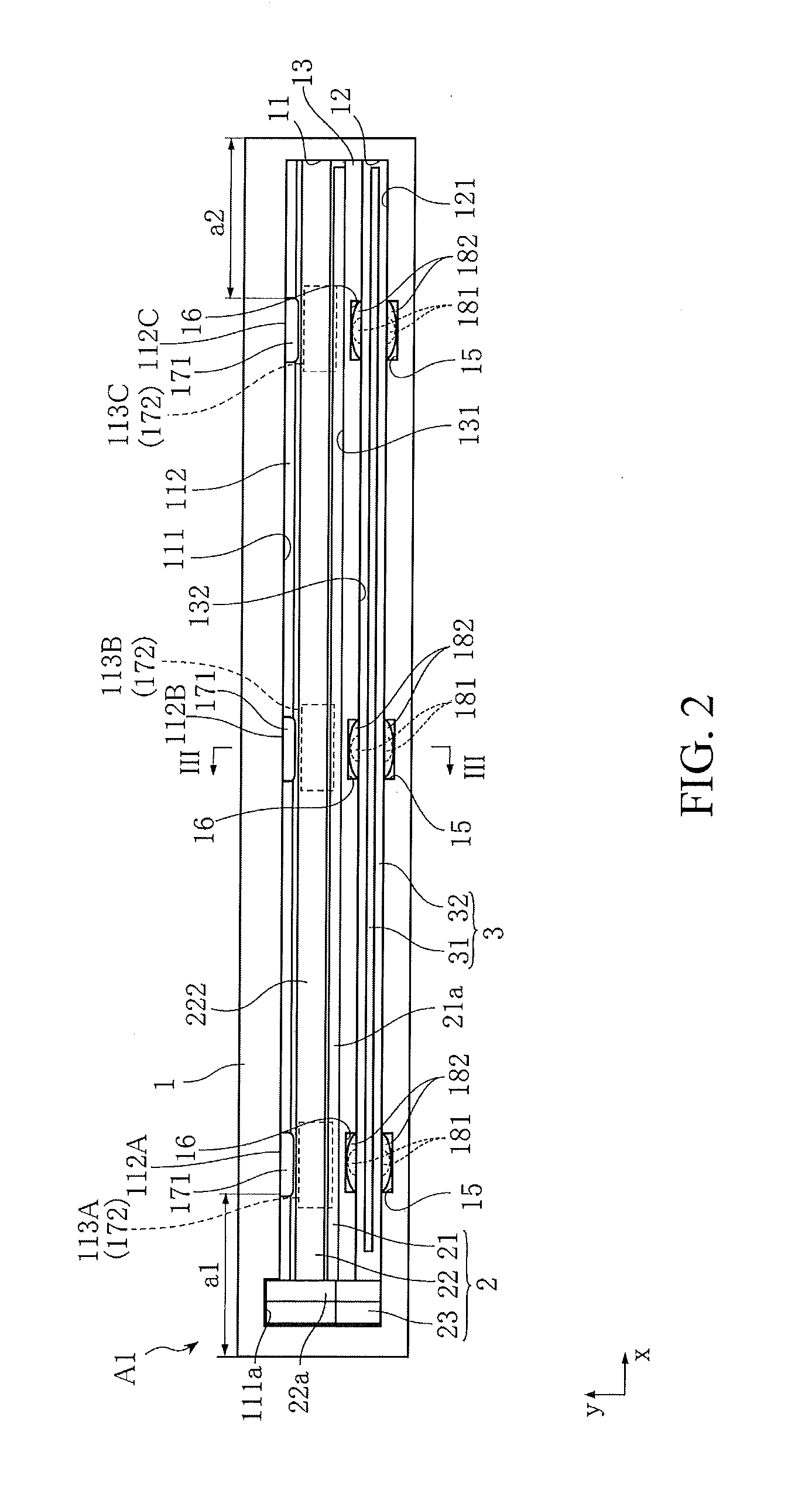
[0091]FIG. 13 shows an image reading device according to the present invention. The difference between the image reading device A2 shown in FIG. 13 and the image reading device A1 lies in positions of the first adhesives 181 and the second adhesives 182 of the three pairs of adhesive disposing cavities 15 and 16; otherwise the formation is the same as that of the image reading device A1. In FIG. 13, for convenience of description, one pair of adhesive disposing cavities 15 and 16 is enlarged.

[0092]In this embodiment, as shown in the enlarged portion of FIG. 13, the first adhesive 181 is coated on two end portions of each of the adhesive disposing cavities 15 and 16 in the x direction. The second adhesive 182 is coated by filling the adhesive disposing cavities 15 and 16.

[0093]In the image reading device A2 (like the image reading device A1), during manufacturing, the lens array 3 is fixed in the lens accommodating portion 12 by using the first adhesive 181 hardened in a short time w...

fifth embodiment

[0100]FIG. 17 shows an image reading device according to the present invention. The difference between the image reading device A5 shown in FIG. 17 and the image reading device A1 lies in the shape of the concave adhesive disposing portion 15; the formation is otherwise the same as that of the image reading device A1.

[0101]As shown in FIG. 17, the concave adhesive disposing portion 15 of this embodiment is at a lower end in the z direction and is located in a position closer to an upper part of the figure than the lower end of the lens array 3 in the z direction.

[0102]The image reading device of the present invention is not limited to the embodiments. The specific formation of parts of the image reading device of the present invention can be designed and changed freely. For example, in the embodiments, the built-in linear light source 2 is formed, but the present invention is also applicable to an image reading device without the linear light source 2 and having only the lens array ...


PUM

PropertyMeasurementUnit
sizeaaaaaaaaaa
sizeaaaaaaaaaa
angleaaaaaaaaaa

Abstract

An image reading device and a method for manufacturing the same are provided, where the image reading device is capable of being assembled more efficiently. The image reading device includes: an optical part, extending long in a direction; a case, having an accommodating portion for accommodating the optical part; and a light receiving component, accommodated in the case. The optical part is fixed in the accommodating portion through a first adhesive and a second adhesive with hardening time longer than that of the first adhesive.

Description

BACKGROUND OF THE INVENTION[0001]1. Field of the Invention[0002]The present invention relates to an image reading device and a method for manufacturing the same.[0003]2. Description of the Related Art[0004]In an apparatus such as a fax machine, a copy machine, or a scanner, an image reading device for reading an original manuscript is installed. FIG. 18 shows an example of the image reading device (for example, referring to Patent Document 1). The image reading device X shown in FIG. 18 includes a case 91, a linear light source 92, a lens array 93, a substrate 94, and a receiving element 95 carried on the substrate 94. The case 91 includes a light source accommodating portion 911 for accommodating the linear light source 92 and a lens accommodating portion 912 for accommodating the lens array 93. The linear light source 92 includes a light guiding body 921 extending long in a main scanning direction and a white case 922 for accommodating the light guiding body 921. An opening is for...

Claims


Application Information

Patent Timeline
Patent Type & Authority Patents(United States)
IPC IPC(8): H04N1/04
CPCH04N2201/03112H04N2201/03141H04N2201/03125H04N1/0318H04N2201/03145H04N2201/03191Y10T156/10
Inventor NAKAMURA, KUNIAKI
Owner ROHM CO LTD
Why Eureka
Try Eureka