Security camera

Inactive Publication Date: 2007-02-22
SAMSUNG ELECTRONICS CO LTD
View PDF6 Cites 49 Cited by
  • Summary
  • Abstract
  • Description
  • Claims
  • Application Information

AI Technical Summary

Benefits of technology

[0013] A first feature of the present invention is to provide a security camera in which connection of electric wires connected between a fixed circuit board install

Problems solved by technology

Fixed-type cameras have a drawback in that the observation direction is fixed, thereby requiring a pl

Method used


Image

  • Security camera
  • Security camera
  • Security camera

Examples


Example

[0043] Throughout the drawings, the same drawing reference numerals will be understood to refer to the same elements, features, and structures.

DETAILED DESCRIPTION OF EXEMPLARY EMBODIMENTS

[0044] Hereinafter, detailed configurations of a security camera in accordance with exemplary embodiments of the present invention are described in detail with reference to the accompanying drawings.

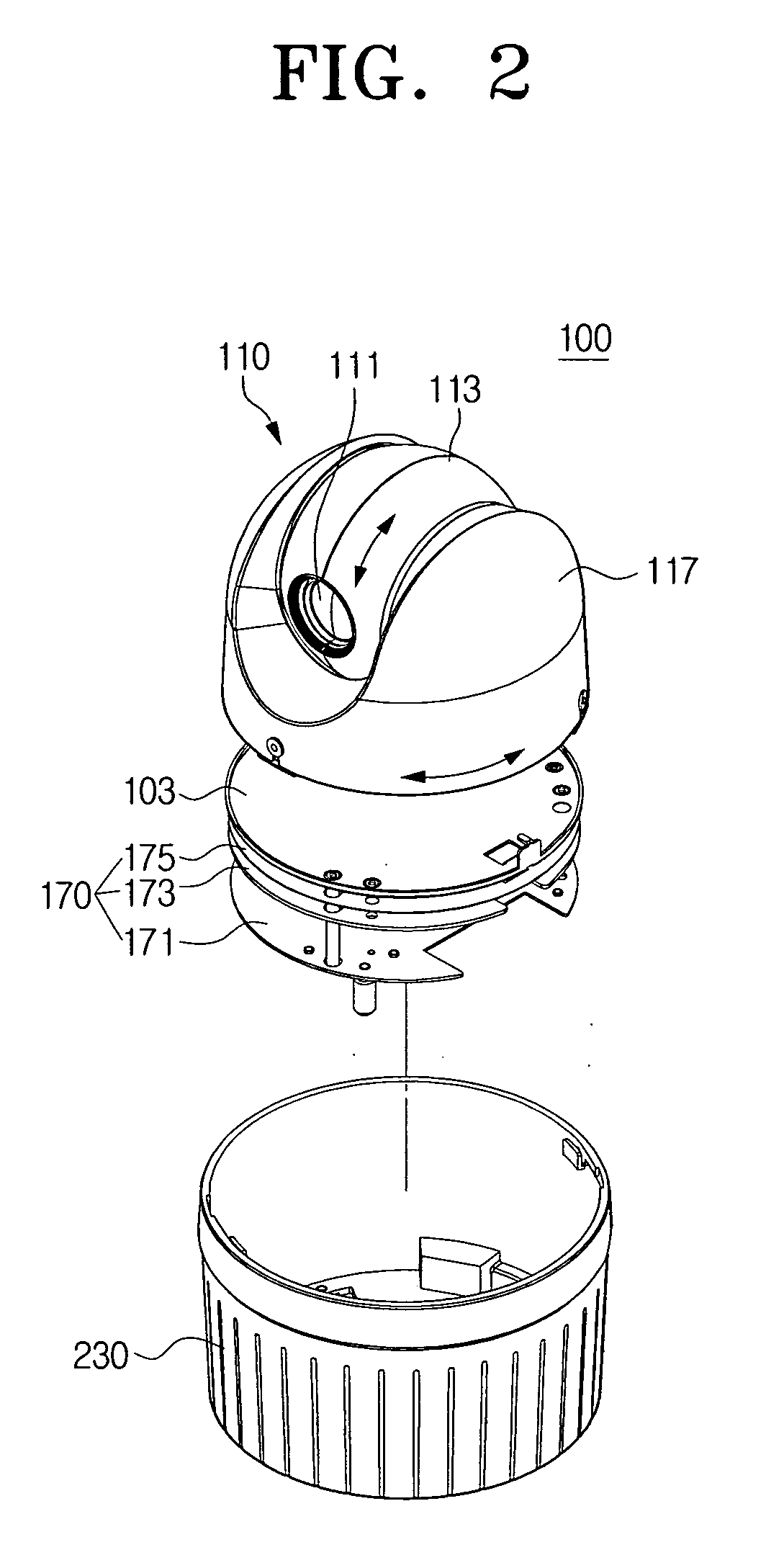
[0045]FIG. 2 is a perspective view of the security camera in accordance with an exemplary embodiment of the present invention.

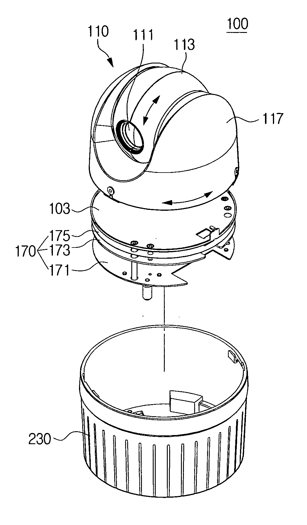
[0046] Referring to FIG. 2, a security camera 100 includes a camera unit 110, a power unit 170 and a case body 230.

[0047] The camera unit 110 has a camera lens module 111. A first housing 113 supports the camera lens module 111 to be rotatable upwardly and downwardly. A second housing 117 is rotatable leftwardly and rightwardly and houses the first housing 113 in which the camera lens module 111 is housed.

[0048] The power unit 170, which supplies a converted voltage necessa...


PUM


Abstract

A security camera includes a camera unit, and a top plate rotatably supporting the camera unit. A movable circuit board is disposed above the top plate. A fixed circuit board is rotatably disposed to be spaced from the movable circuit board by a predetermined gap. An electric wire electrically connects the movable circuit board and the fixed circuit board. A slip ring substantially prevents the connection electric wire from being twisted by rotational movement of the movable circuit board. A connection unit supports the slip ring and rotatably supports the top plate.

Description

CROSS REFERENCE TO RELATED APPLICATION [0001] This application claims the benefit under 35 U.S.C. §119(a) from Korean Patent Application No. 2005-76484, filed on Aug. 19, 2005, the entire content of which is hereby incorporated by reference. BACKGROUND OF THE INVENTION [0002] 1. Field of the Invention [0003] The present invention relates to a security camera. More particularly, the present invention relates to a security camera that has an improved electric wire connecting part connected to a fixed circuit board and to a movable circuit board, and an improved assembling structure of a rotation supporting part rotatably supporting a camera. [0004] 2. Description of the Related Art [0005] Generally, security cameras are being used more frequently in many places, such as residential streets, parking lots, department stores, banks, exhibition halls, and so forth, to prevent illegal acts, such as robberies, from being committed. [0006] The aforementioned security cameras are classified i...

Claims


Application Information

Patent Timeline
IPC IPC(8): G03B17/00
CPCG03B17/02G03B37/02G08B13/1963H04N7/18
Inventor LEE, WOON-HO
Owner SAMSUNG ELECTRONICS CO LTD
Why Eureka
Try Eureka