Connecting element for the non-detachable connection of at least two components and composite arrangement

Pending Publication Date: 2020-09-24
ARNOLD UMFORMTECHN
View PDF1 Cites 0 Cited by
  • Summary
  • Abstract
  • Description
  • Claims
  • Application Information

AI Technical Summary

Benefits of technology

[0008]It is therefore the object of the present invention to eliminate or at least partially eliminate the disadvantages described above with regard to a connecting element or joining element. In particular, it is the object of the present invention to provide a connecting element for the non-detachable joining of at least two components

Problems solved by technology

However, this demand can collide with technical boundary conditions, such as a high axial force on the joining element when joining by friction welding, which results in an increase in the processing time, or with the demand for a reduction in the quantity of metal chips when the joining element is turned.
Problems are associated with such processing, such as an increase

Method used


Image

  • Connecting element for the non-detachable connection of at least two components and composite arrangement
  • Connecting element for the non-detachable connection of at least two components and composite arrangement
  • Connecting element for the non-detachable connection of at least two components and composite arrangement

Examples


Example

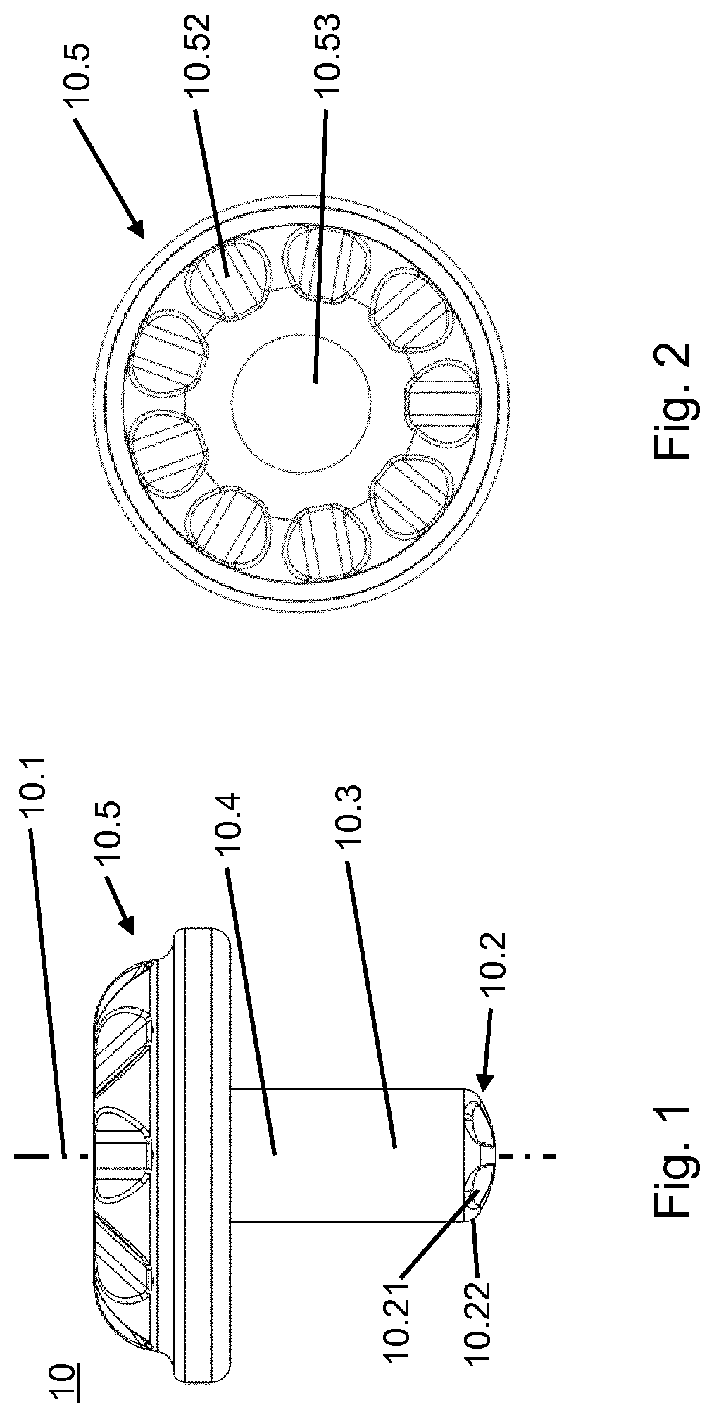
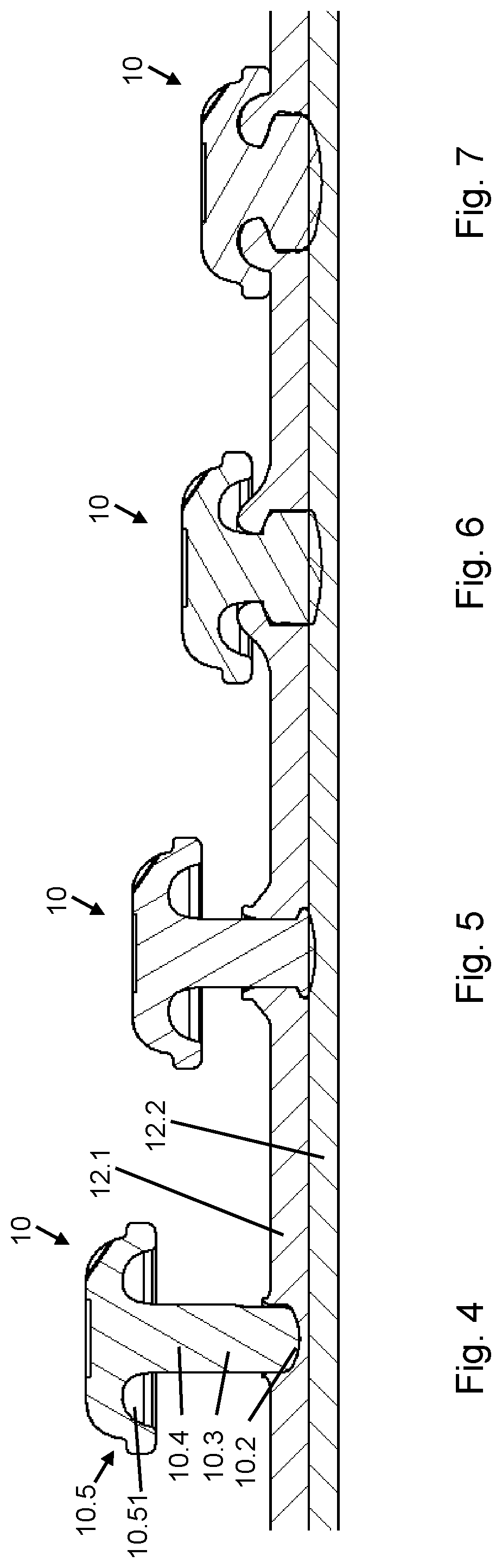
[0073]FIG. 1 shows a first embodiment of connecting element 10, which is used for the non-detachable connection of two components 12.1, 12.2 by friction welding, which is used in the FIG. 4-7, when turning the connecting element 10 around a longitudinal axis 10.1 of the connecting element 10.

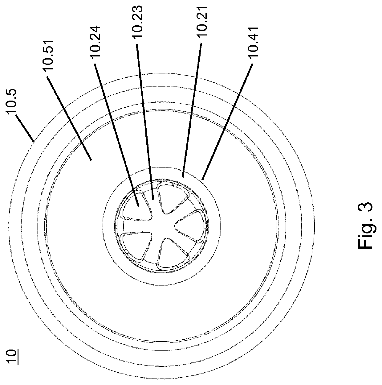
[0074]The connecting element 10 comprises:[0075]a stem 10.2-10.4 formed along the longitudinal axis 10.1 with a stem face 10.2 at a free end of the stem 10.2-10.4 for penetrating a component 12.1, and[0076]a head 10.5 connected to the stem 10.2-10.4 to transmit a torque about the longitudinal axis 10.1 from a turning tool to the stem 10.2-10.4.

[0077]The stem face 10.2 has a stem end face 10.21 which has a convex envelope 10.22 with a blunt course. The envelope 10.22 of the stem end face 10.21 is to be understood as a surface which envelops the stem end face 10.21 and whose points connect relative maxima of the stem end face 10.21 (see FIG. 8-10). The relative maxima form points of a 2D interpola...


PUM

PropertyMeasurementUnit
Lengthaaaaaaaaaa
Thicknessaaaaaaaaaa
Diameteraaaaaaaaaa

Abstract

The present invention relates to a connecting element for non-detachably connecting at least two components by means of friction welding when the connecting element is rotated about a longitudinal axis of the connecting element. The connecting element includes a stem formed along the longitudinal axis with a stem face at a free end of the stem for penetrating at least one component, and a head connected to the stem for transmitting a torque about the longitudinal axis from a turning tool to the stem. The stem face has a stem end face which has a convex envelope with a blunt shape.

Description

CROSS REFERENCE TO RELATED APPLICATION[0001]This application claims the benefit under 35 U.S.C. § 119(a) of German Application No. 10 2017 221 681.6 filed on Dec. 1, 2017 and is a national stage application under 35 U.S.C. § 371, of PCT / EP2018 / 080685, filed on Nov. 8, 2018, the contents of both are incorporated by reference herein in their entirety.BACKGROUND OF THE DISCLOSURE1. Field of the Disclosure[0002]The present invention relates to a connecting element for the non-detachable joining of at least two components by means of friction welding, as well as a composite arrangement with at least one connecting element which connects at least two components by means of friction welding.2. Description of the Related Art[0003]In the automated joining technology of metallic materials or components, the processing time or processing speed represents an essential productivity and cost factor. The demand for shorter processing times is therefore widespread. However, this demand can collide ...

Claims


Application Information

Patent Timeline
IPC IPC(8): F16B9/00
CPCF16B9/01B23K35/0288F16B5/08F16B37/061B23K35/3053B23K35/3073B23K35/325B23K35/02B21J15/027B23K20/1295B23K35/286B23K35/302
Inventor FRÖHLICH, DOMINIKVOGEL, GEORGPHILIPP, ANDREASROMINGER, PATRICKTRUETSCH, KLAUS
Owner ARNOLD UMFORMTECHN
Why Eureka
Try Eureka