Rivet tool for steel studs

Inactive Publication Date: 2009-02-12
HASSENZAHL ROBERT D
View PDF33 Cites 9 Cited by
  • Summary
  • Abstract
  • Description
  • Claims
  • Application Information

AI Technical Summary

Benefits of technology

[0011]The subject apparatus and method provides an efficient method of joining steel framing members using self-punching rivets which are easier and faster than prior art fastening methods, and which can be counter-sunk by deforming the sheet metal around the head of the self-punching rivet so as to improve the strength of the joint. A sheet metal joint made according to t

Problems solved by technology

Nevertheless, steel framing is used only in an estimated 3-5% of residential building projects.
In part, steel framing has not achieved wide-spread acceptance because the required assembly tools and skills are different from those of wood framing, which is a disadvantage for do-it-yourselfers and smaller construction companies.
A drawback of this technique resides in the screw head which is left standing proud of the steel stud, because the screw head is not counter sunk into the sides of the sheet metal.
The protruding head presents difficulties when wallboard, for example, drywall or paneling, is applied over the framed wall.
Lumps in the wallboard may result, and even damage to the wallboard if not properly handled.
If the wallboard is affixed by adhesive, the raised screw heads can create excessive glue joints and thus weaken the construction.
There have been prior attempts to use a form of pneumatically driven nail in s

Method used


Image

  • Rivet tool for steel studs
  • Rivet tool for steel studs
  • Rivet tool for steel studs

Examples


Example

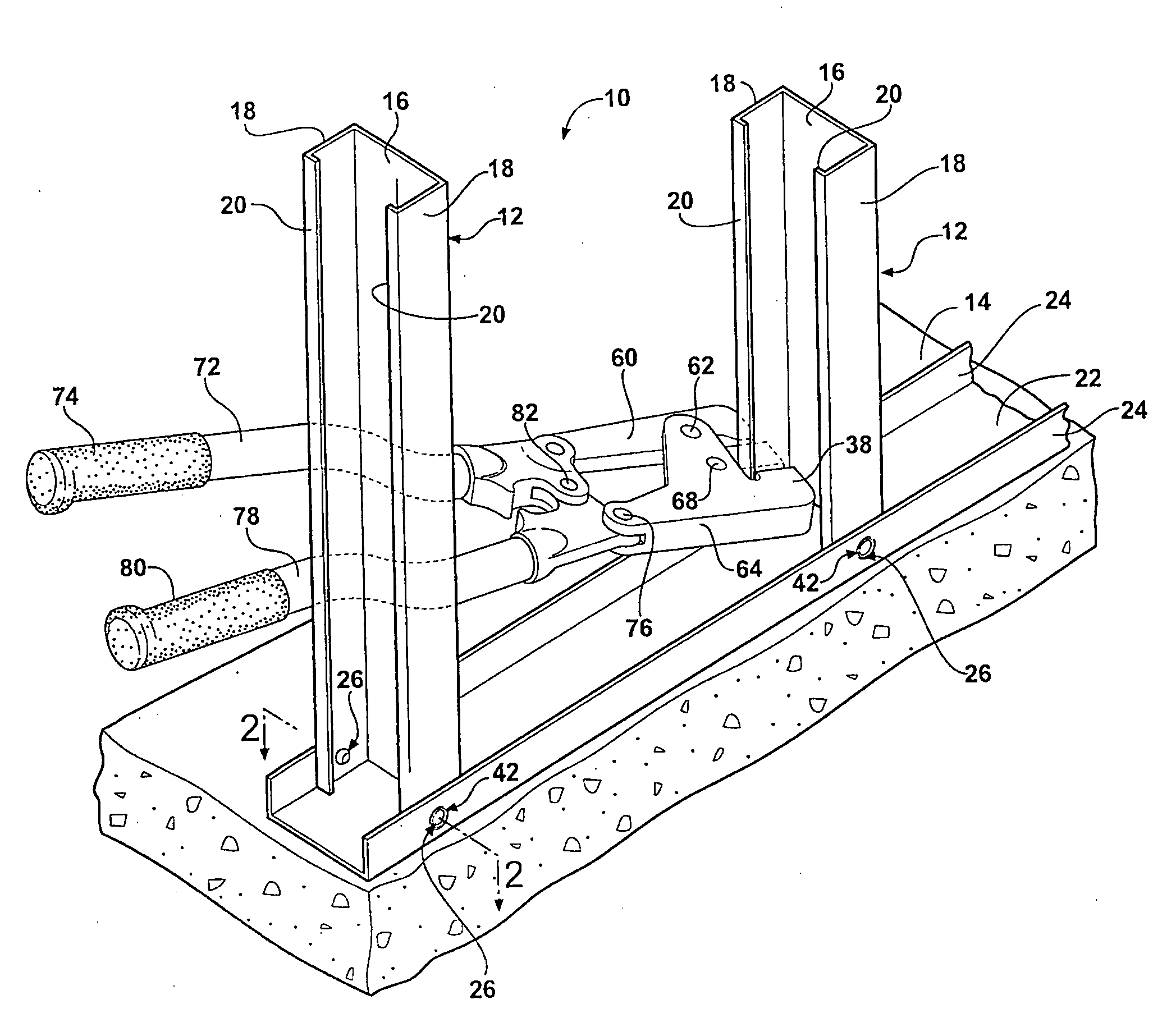
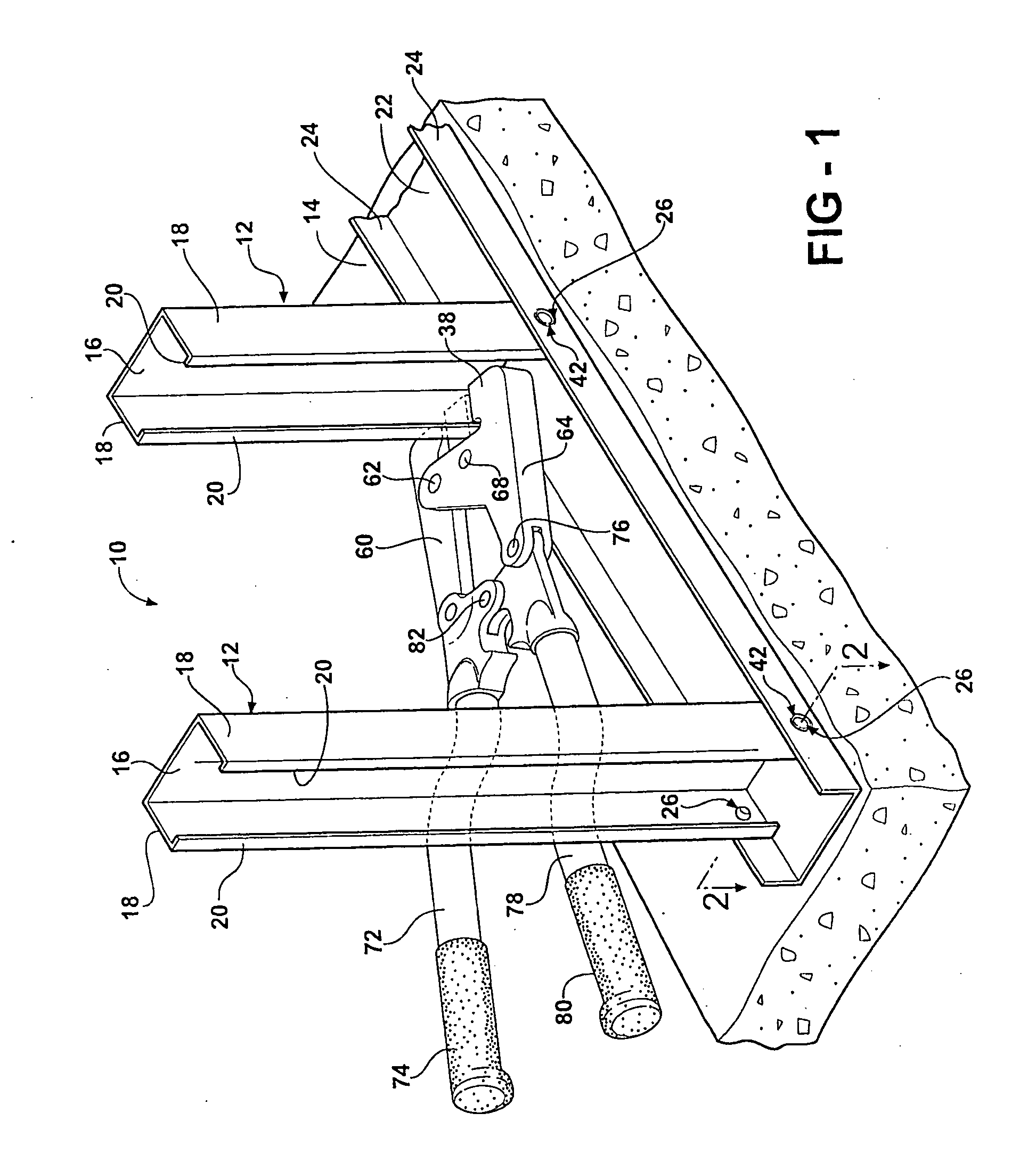
[0021]Referring to the Figures, wherein like numerals indicate like or corresponding parts throughout several views, a typical steel frame wall 10 under construction is generally shown in FIG. 1 including vertical studs 12 fastened to a bottom track 14. The studs 12 and bottom track 14 are here used only for illustrative purposes as those skilled in the art will understand that other structural components, such as a top track, cross members, trusses, beams, brackets and the like also made from formed sheet metal can be joined in the same fashion as those components illustrated in FIG. 1. Therefore, while the following description will reference the joining of a stud 12 to a bottom track 14, it must be understood that any other sheet metal joining requirements can be addressed using the method and apparatus of the subject invention.

[0022]As is well-known in the art, the studs 12 of a steel frame wall 10 extend between opposite ends thereof and have a generally C-shaped cross-section....


PUM

PropertyMeasurementUnit
Yield pointaaaaaaaaaa

Abstract

An improved method for constructing a steel stud frame wall (10) or other sheet metal joining applications using self-punching rivet fasteners (26). The steel stud frame wall includes discrete members to be joined, such as studs (12) connected to a bottom (or top) track (14). A rivet (26) is driven from the outside and staked on the inner, blind side of the overlapping regions of sheet metal. A leading tip (32) of the rivet (26) punches a chad (54) and is then deformed in a die cavity (40) of a setting tool to lock the formed steel pieces in position. The head (28) of the rivet (26) is pressed into the sheet metal during the setting operation so that a pocket (42) is formed out of the surrounding sheet metal, the pocket (42) having at least two distinct contours (56, 58) formed around the rivet head (28). The pocket (42) allows the rivet head (28) to seat into the outer surface of the sheet metal, thus facilitating a subsequent covering operation with wallboard (98) or the like. The multiple distinct contours (56, 58) of the pocket (42) substantially enhances the joint integrity in both sheer and rotational directions. The punched chad (54) helps avoid the introduction of stress cracks in the sheet metal, thereby enhancing joint integrity. A tool for setting the rivet (26) can be actuated mechanically, pneumatically, hydraulically, electrically, by combustion or any other known process.

Description

RELATED APPLICATIONS[0001]This invention relates to, and claims the benefit of priority from U.S. Provisional Application No. 60 / 619,187 filed Oct. 15, 2004.BACKGROUND OF THE INVENTION[0002]1. Field of the Invention[0003]The invention relates generally to a method and apparatus for fastening two overlapping sheets of metal with a deformable rivet, and more specifically toward an apparatus and method for fastening steel framing members with a rivet whose head is used to form a multi-contoured pocket in the sheet metal members.[0004]2. Related Art[0005]Steel framing members are used in the construction industry to fabricate walls and other structural elements. Unlike wood, steel framing does not warp, shrink or split. It is not vulnerable to termites or carpenter ants. It will not rot, crumble, or add fuel to a fire. Because of this, and its strength and durability, steel framing has become a standard for commercial construction. Nevertheless, steel framing is used only in an estimate...

Claims


Application Information

Patent Timeline
IPC IPC(8): B23P11/00E04C3/04
CPCB21J15/025B21J15/10B21J15/18Y10T29/49835B21J15/26B21J15/386B21J15/20
Inventor HASSENZAHL, ROBERT D.
Owner HASSENZAHL ROBERT D
Why Eureka
Try Eureka