
Universal stem shaft handle

Pending Publication Date: 2021-07-29
FINEGAN JR STEPHEN E
View PDF2 Cites 0 Cited by
  • Summary
  • Abstract
  • Description
  • Claims
  • Application Information

AI Technical Summary

Benefits of technology

The present invention provides a novel universal handle that can be easily applied to different sizes and shapes of stem shafts and splines, regardless of their condition, for various types of water spigots, air tanks, and gaseous tanks. The handle is simple and efficient in its application and operation, and it remains readily removable at the option of the user. It is designed to provide an improved ratchet handle system with ergonomic use and economical construction. The handle allows quick adjustment of its positioning upon the intended stem shaft or spline by a user. Additionally, the handle has a visually appealing design element, making it easy to attach and detach from the shaft. The cylindrical chuck body includes jaws with teeth formed on their inner surface, which provides better grip of the outer surface of a stem shaft when clamped thereupon. The jaws in the stem shaft handle have teeth formed on their inner surface to provide better grasp of the intended valve stem shaft.

Problems solved by technology

People around the world encounter broken handles of water valves, particularly exterior spigots used for hose connections, which typically have valves with relatively small diameter stem shafts having damaged splines which make it difficult for mating with conventional replacement handles.
It is often difficult to find replacement valve handles that properly fit the varying sizes of the valve stem shafts.
In addition to being small, typical valve handles are smooth and slippery when wet.
As a result, they are difficult to grip adequately to open or close the valve.
Since the valve handles are oftentimes located close to an obstruction, slippage can cause abrasion injuries to the operator's hand.
These problems are especially difficult for people with reduced or impaired gripping strength, such as some of the elderly or people afflicted with arthritis or other debilitating conditions.
Many such handle devices are not easily securable to damaged stem shafts of variable sizes.
None of such conventional devices disclose the unique structures and advantages of the present disclosure.

Method used


Image

  • Universal stem shaft handle
  • Universal stem shaft handle
  • Universal stem shaft handle

Examples


Embodiment Construction

[0085]For a further understanding of the nature and function of the embodiments, reference should be made to the following detailed description. Detailed descriptions of the embodiments are provided herein, as well as, the best mode of carrying out and employing the present invention. It will be readily appreciated that the embodiments are well adapted to carry out and obtain the ends and features mentioned as well as those inherent herein. It is to be understood, however, that the present invention may be embodied in various forms. Therefore, persons of ordinary skill in the art will realize that the following disclosure is illustrative only and not in any way limiting, as the specific details disclosed herein provide a basis for the claims and a representative basis for teaching to employ the present invention in virtually any appropriately detailed system, structure or manner. It should be understood that the devices, materials, methods, procedures, and techniques described herei...


PUM


Abstract

The present disclosure provides for a stem shaft handle adapted to grasp a stem shaft. The stem shaft handle includes a handle body and a chuck assembly removably connected to the handle body. The chuck assembly includes a cylindrical chuck body having an outer surface with at least one biasing locking protuberance disposed within an outer sleeve defining at least one nodule geometrically configured to fittingly engage the at least one biasing locking protuberance in a locking arrangement. In a preferred embodiment, the cylindrical chuck body has a concentrically disposed cylindrical plate which defines at least one nonconcentrically disposed aperture adapted to receive at least one nonconcentrically disposed retention member in a lock and key style geometric alignment and is removeably connected to the handle body. In other preferred embodiments the handle body defines an inner cavity having a geared ratchet assembly or a gearless ratchet assembly disposed therein.

Description

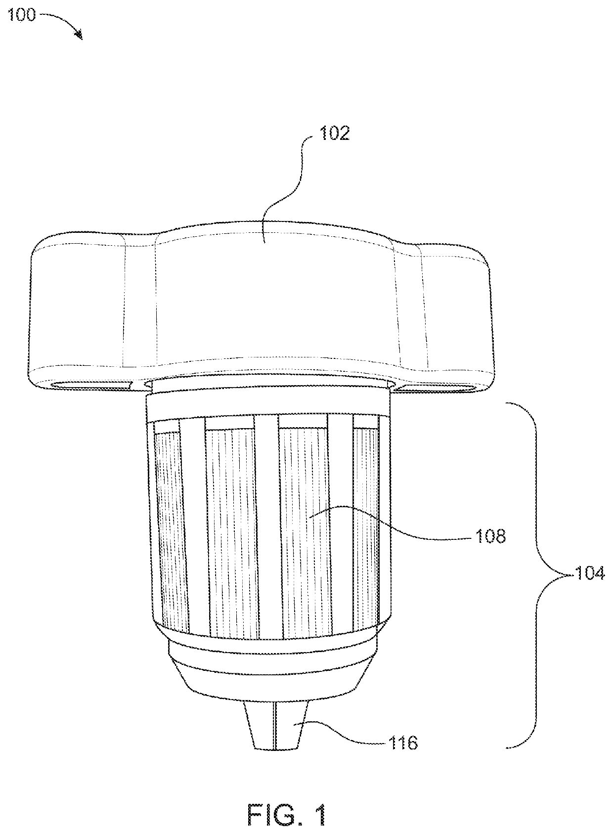
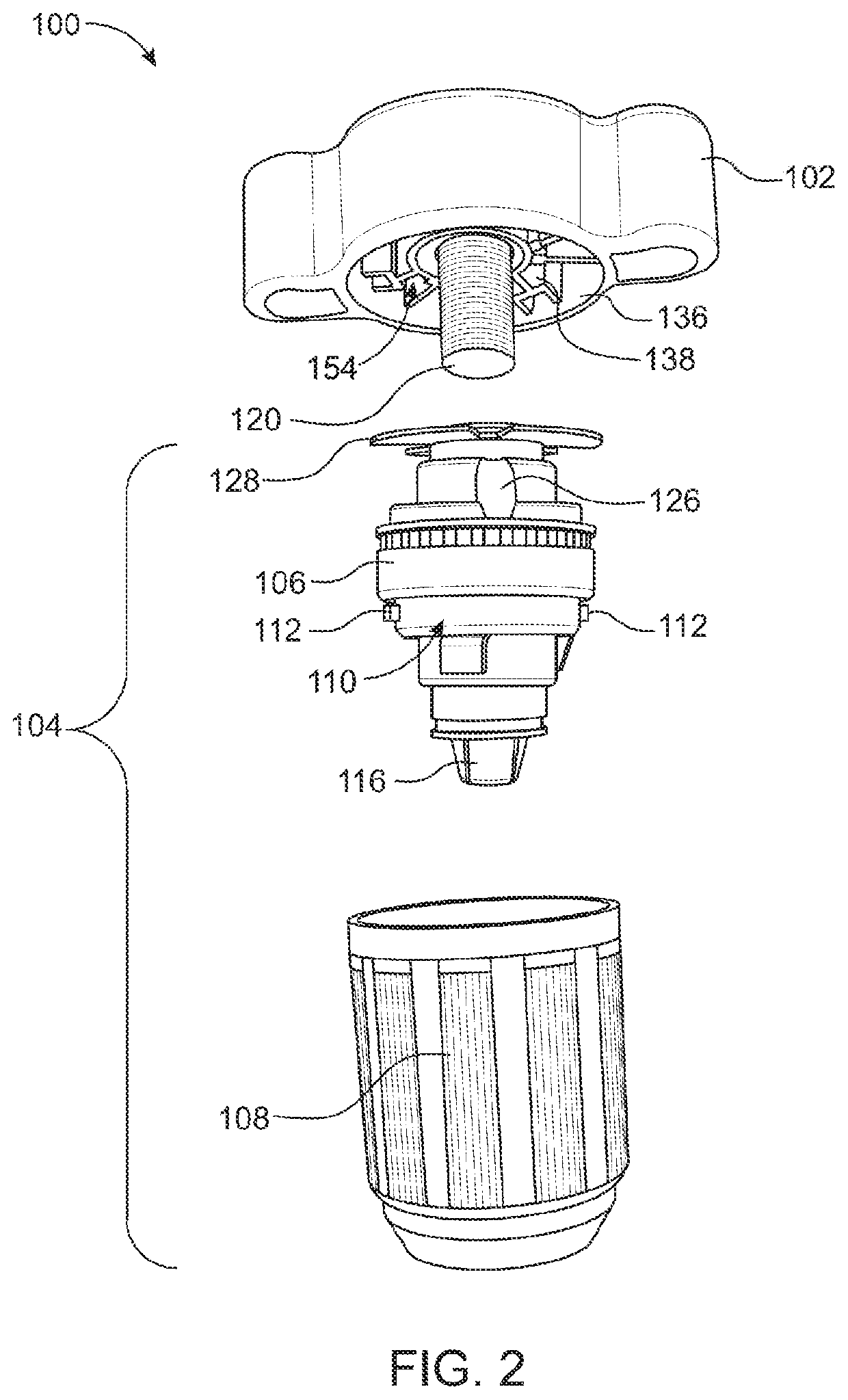
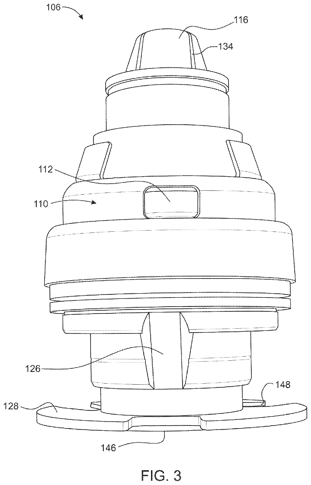
BACKGROUND OF THE INVENTIONField of the Invention[0001]The present invention generally relates to stem shaft handles and more particularly relates to valve stem shaft handle devices which can be removably coupled to a stem shaft of universal size, configuration, and condition.Description of the Related Art[0002]People around the world encounter broken handles of water valves, particularly exterior spigots used for hose connections, which typically have valves with relatively small diameter stem shafts having damaged splines which make it difficult for mating with conventional replacement handles. It is often difficult to find replacement valve handles that properly fit the varying sizes of the valve stem shafts. In addition to being small, typical valve handles are smooth and slippery when wet. As a result, they are difficult to grip adequately to open or close the valve. Since the valve handles are oftentimes located close to an obstruction, slippage can cause abrasion injuries to ...

Claims


Application Information

Patent Timeline
IPC IPC(8): F16K31/60G05G1/08
CPCF16K31/60G05G1/08
Inventor FINEGAN, JR., STEPHEN E.
Owner FINEGAN JR STEPHEN E
Learn More