System for regulating current flow to a plurality of electrical devices

Inactive Publication Date: 2013-05-14
HERNANDEZ MAURILIO G
View PDF23 Cites 0 Cited by
  • Summary
  • Abstract
  • Description
  • Claims
  • Application Information

AI Technical Summary

Benefits of technology

[0015]Additional features of the system of the present invention include the hardware structure in which it is embodied. More specifically, one preferred embodiment of the present invention comprises a housing dimensioned and configured to encase the operative components of at least the control assembly including, but not limited to, the timing circuitry, timing device, etc. associated with the timing assembly as well as the switches, indicators, and other operative circuitry and components associated with the operation of the plurality of outlet sections and the connection and switching capabilities relating to the first and second power inlets. Moreover, each of the outlet sections and more specifically each of the one or more outlets associated with each outlet section are located in an exteriorly exposed position. As such, the various electrical devices can be efficiently connected to intended or appropriate ones of the outlets of each of the plurality of outlet sections.
[0016]Other structural features associated with the housing may include a physical representation and/or display of the timing assembly in the form of a manually or remotely operated timing device. Moreover, the timing device may include a selector, which facilitates an initial and subsequent, manual or automatic, selection of the preset lengths of time of operability of the one or more plurality of outlet sections. More specifically, these preset times, as set forth above, define the aforementioned variable ranges of time periods which may be selected before current flow from the at least first power input is terminated to the one or more outlet sections connected thereto. However, as set forth in greater detail

Problems solved by technology

Further, the limitation of wall sockets throughout a given commercial or domestic environment often requires the use of “power strip

Method used


Image

  • System for regulating current flow to a plurality of electrical devices
  • System for regulating current flow to a plurality of electrical devices
  • System for regulating current flow to a plurality of electrical devices

Examples


Example

[0027]Like reference numerals refer to like parts throughout the several views of the drawings.

DETAILED DESCRIPTION OF THE PREFERRED EMBODIMENT

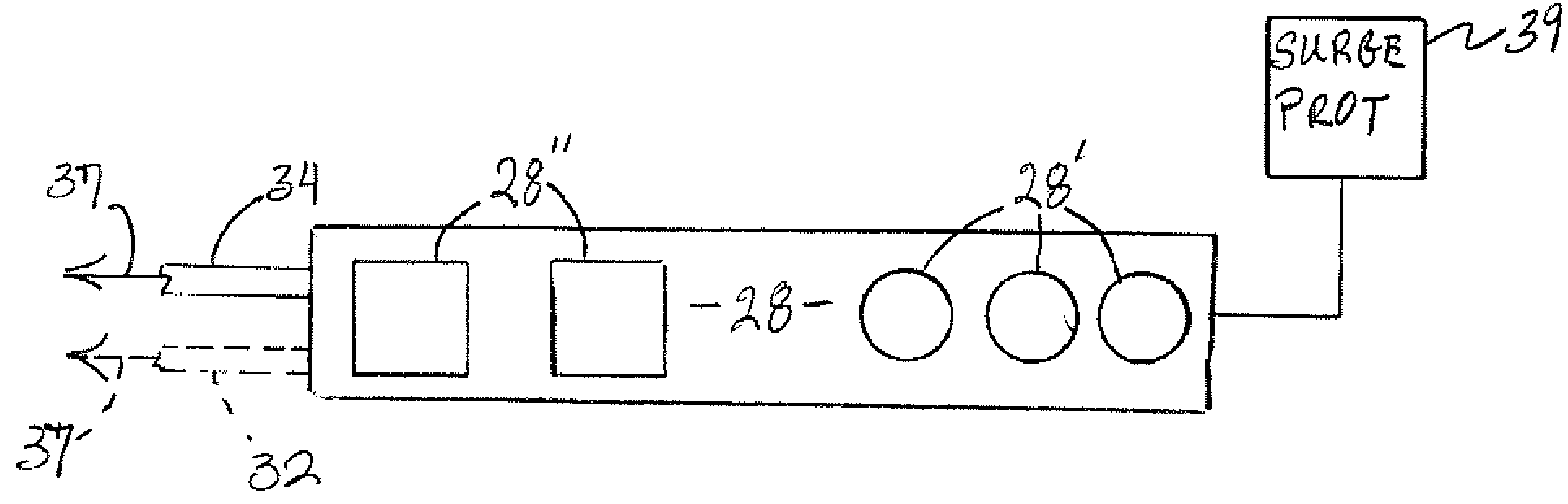
[0028]The present invention is directed to a system for regulating the flow of electrical current to a plurality of electrical devices such as, but not limited to, audio and video components associated with an entertainment center, peripherals associated with a computer station. Moreover, the system of the present invention can be used to regulate the delivery of current to a wide variety of electrically powered devices especially, but not exclusively, wherein such devices are utilized concurrently or as an overall assembly, such as in the aforementioned entertainment center.

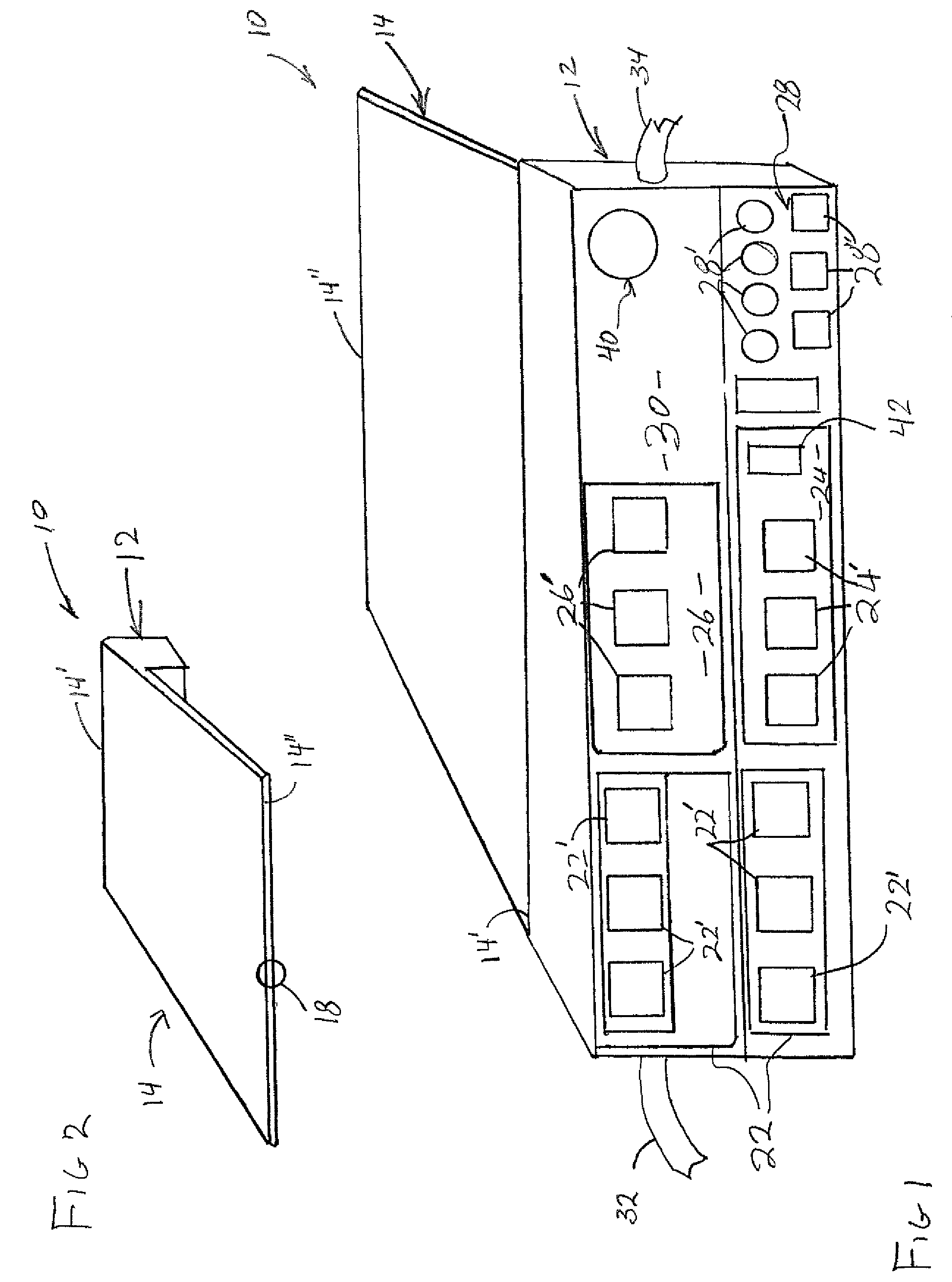
[0029]Therefore, the regulating system of the present invention is embodied in a console or hardware component generally indicated as 10 in FIGS. 1 and 2. The component 10 includes a housing generally indicated as 12 and a mounting structure, generally indicated as 14, se...


PUM


Abstract

A system for selectively regulating current flow to a plurality of electrical devices, being at least partially operative by wireless remote control and including a control assembly connected to at least a first power input and a second power input. The control assembly includes a plurality of outlet sections, each including at least one outlet structured to electrically connect an electrical device to either the first or second power inputs. A timing assembly is operatively structured for time based regulation of current flow from one of the power inputs to one of the outlet sections, wherein another outlet section includes switching capabilities structured to selectively establish a current flow connection with either the first or second power input. A receiver assembly is operatively connected to at least the timing assembly and structured for wireless, operative activation with a remote transmitting unit.

Description

BACKGROUND OF THE INVENTION[0001]1. Field of the Invention[0002]This invention is directed to a system for selectively and automatically regulating current flow to a plurality of electrical devices primarily, but not exclusively, utilizing wireless remote control communication. A control assembly is connected to first and second power outputs and includes a plurality of outlet sections, each of which include at least one outlet. A timing assembly is structured for time based regulation of current flow from one of the power inputs to at least one of the plurality of outlet sections, wherein current flow to this one section is automatically terminated upon the uninterrupted expiration of a given, preset period of time.[0003]2. Description of the Related Art[0004]Various types of electrical devices, such as those associated with home entertainment centers, computer peripherals, as well as larger kitchen type appliances are known to be operated at least partially through the use of wire...

Claims


Application Information

Patent Timeline
IPC IPC(8): H02J1/10
CPCH02J3/005H02J3/007
Inventor HERNANDEZ, MAURILIO G.
Owner HERNANDEZ MAURILIO G
Why Eureka
Try Eureka