
Entertainment machine having a signal-generating device coupled to a movable symbol-bearing support

Inactive Publication Date: 2011-08-18
IGT
View PDF100 Cites 1 Cited by
  • Summary
  • Abstract
  • Description
  • Claims
  • Application Information

AI Technical Summary

Benefits of technology

[0013]With this arrangement instead of requiring a specially printed reel band it is possible to use a standardized reel and support and then produce the desired symbols by appropriate signal-actuation of the support. Initial set up and possibly also subsequent change of the symbols can thereby be much facilitated and special visual effects can be readily incorporated.

Problems solved by technology

The use of attached, printed reel bands is generally inconvenient and restrictive.
It means that different symbol combinations require printing of different reel bands, and changes cannot readily be implemented to existing operational machines.
Also, reliance on printing limits the ability conveniently to incorporate and change special visual effects.
This permits ready set up and subsequent change of symbols and permits easy incorporation of special visual effects, but simulated reels are not always as acceptable to players as mechanical reels.

Method used


Image

  • Entertainment machine having a signal-generating device coupled to a movable symbol-bearing support
  • Entertainment machine having a signal-generating device coupled to a movable symbol-bearing support
  • Entertainment machine having a signal-generating device coupled to a movable symbol-bearing support

Examples


Embodiment Construction

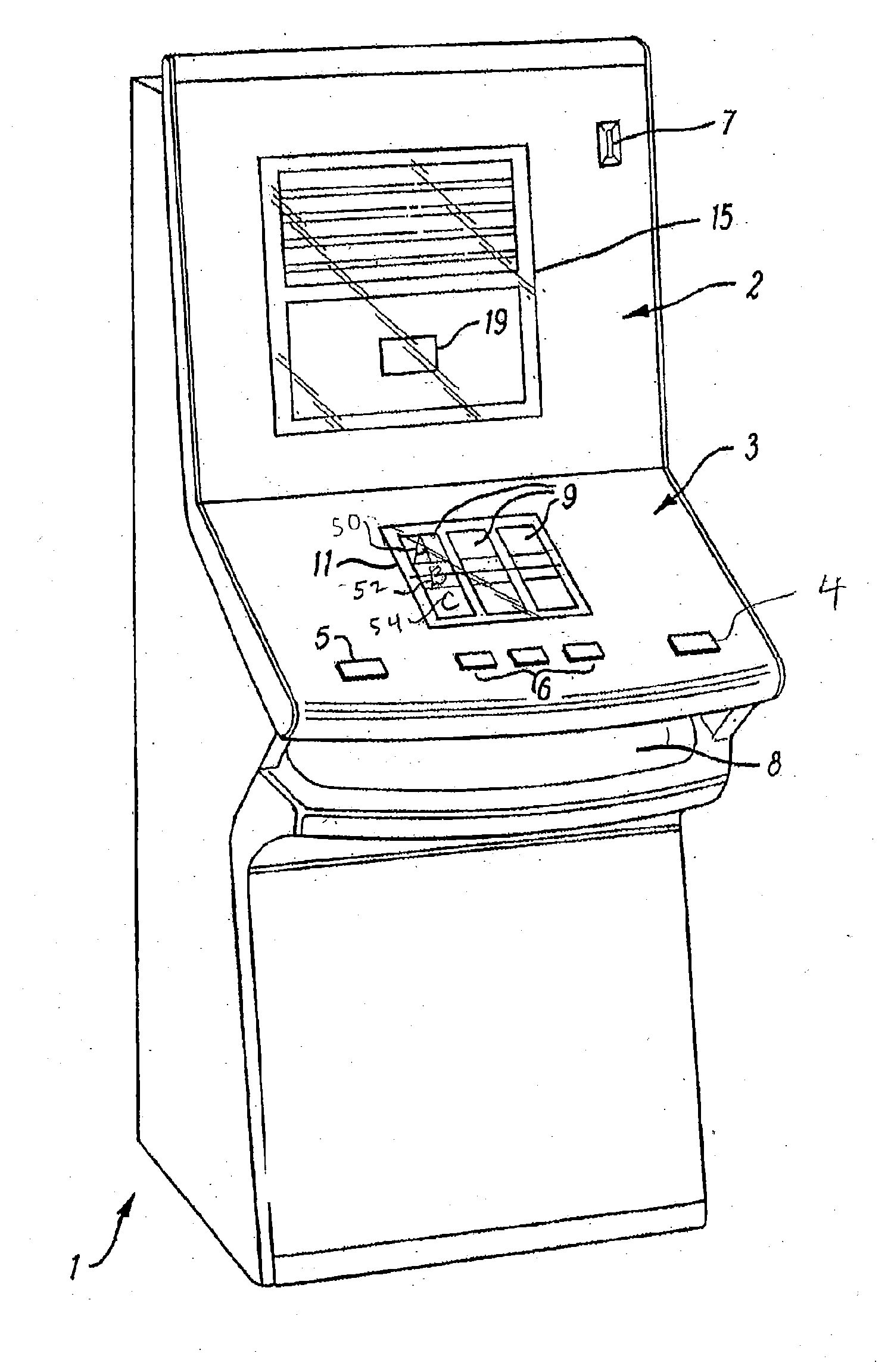
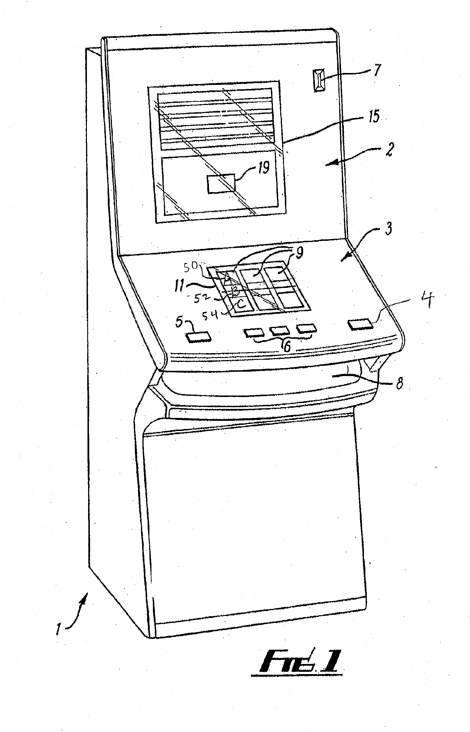
[0047]Referring to the drawings, FIG. 1 shows a fruit machine having a floor-standing box shaped housing 1 having a front wall which includes upper and lower glass panels, 2,3, a number of operating buttons 4,5,6, a coin slot 7 and a payout opening 8.

[0048]Within the housing 1 there are three axially aligned reels 9 having say 20 symbols at regularly spaced positions around their peripheries. The reels 9 are axially rotatable and are drivably connected to respective stepper motors 10. The reels 9 are arranged behind a window 11 defined by a printed region of the lower glass panel 3. Each reel 9 can be arrested by the respective stepper motor 10 in any of 20 stopping positions in which one symbol is in precise registration with a horizontal win line in the centre of the window 11 and two further symbols are visible above and below the win line.

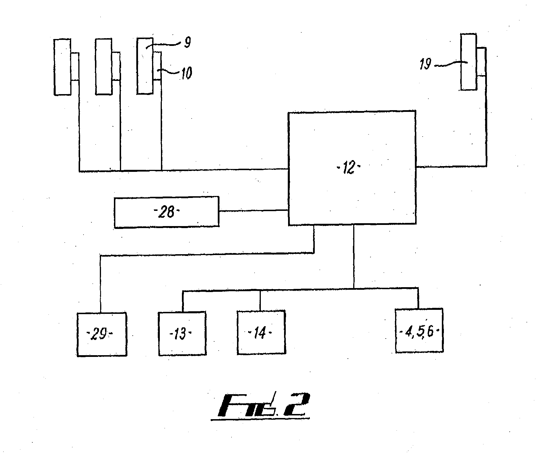
[0049]The stepper motors 10 are connected to a microprocessor-based control unit 12. This unit is also connected to a coin-mechanism 13, a pay...


PUM


Abstract

An entertainment machine having a display device including a rotatable reel with symbols around its periphery. The symbols are defined digitally on a support, such as a curved LCD strip, by feed of signals from a signal generating device. The support may rotate with the reel. Alternatively the support may be fixed so that the reel rotates but the support is static. In this case, the support extends round part only of the periphery of the reel and the feed of signals is such as to define symbols which move with the rotation of the reel.

Description

PRIORITY CLAIM[0001]This application is a continuation of, and claims priority to and the benefit of, U.S. patent application Ser. No. 10 / 511,459, filed on Mar. 7, 2005, which is a §371 national phase application of PCT / GB03 / 01409, filed on Apr. 1, 2003, which claims priority to GB Application Serial No. 0208533.0, filed on Apr. 13, 2002, the contents of which are hereby incorporated by reference in their entirety.BACKGROUND[0002]This invention relates to player-operable entertainment machines, particularly coin-operated amusement with prizes (AWP) machines, such as “fruit” or “poker” machines of the kind having a main display device for displaying a selected combination of symbols at a win zone. As used herein the term coin is intended also to cover tokens, charge or credit cards or any other means of supplying credit or monetary value.[0003]The main display device of a fruit machine may comprise multiple (usually three or four) side-by-side reels which are rotatable about a common...

Claims


Application Information

Patent Timeline
IPC IPC(8): A63F9/24A63F13/08G07F17/32G07F17/34
CPCG07F17/3213G07F17/3211G07F17/34
Inventor RANDALL, DOV L.
Owner IGT
Learn More