Central Tire Inflation Wheel Assembly, Valve and Central Tire Inflation System

a technology of central tire inflation and tire inflation, which is applied in the direction of functional valve types, instruments, transportation and packaging, etc., can solve the problems of valve failure, valve damage, and increase the cost and complexity of valves, so as to increase improve the longevity of valves, and simplify the valve construction

Inactive Publication Date: 2013-10-24
MEDLEY MARTIN A +1
View PDF8 Cites 32 Cited by
  • Summary
  • Abstract
  • Description
  • Claims
  • Application Information

AI Technical Summary

Benefits of technology

[0010]According to one aspect of the present disclosure, a tire valve is provided that can be seated directly on or within a tire wheel and includes a minimum of moving parts to simplify the construction of the valve and to increase the longevity of the valve. The valve includes a casing that is secured to the wheel rim to position the valve on the exterior of the rim or in a position where the valve is located in a recessed position with regard to the rim. The casing encloses a main body that is positioned within the casing in a sealed configuration to prevent air flow between the casing and the main body. The casing also includes an aperture that positions the main body in communication with an air supply used to inflate the tires of a vehicle such that the air supply can direct an air flow through the main body to the tire though an outlet in the casing. To control the air flow from the air supply, the main body incl

Problems solved by technology

These additional components greatly increase the cost and complexity of the valves and the associated CTIS, causing the valves to fail on a regular basis, necessitating that the valves be repaired and/or replaced on a consist

Method used


Image

  • Central Tire Inflation Wheel Assembly, Valve and Central Tire Inflation System
  • Central Tire Inflation Wheel Assembly, Valve and Central Tire Inflation System
  • Central Tire Inflation Wheel Assembly, Valve and Central Tire Inflation System

Examples


first embodiment

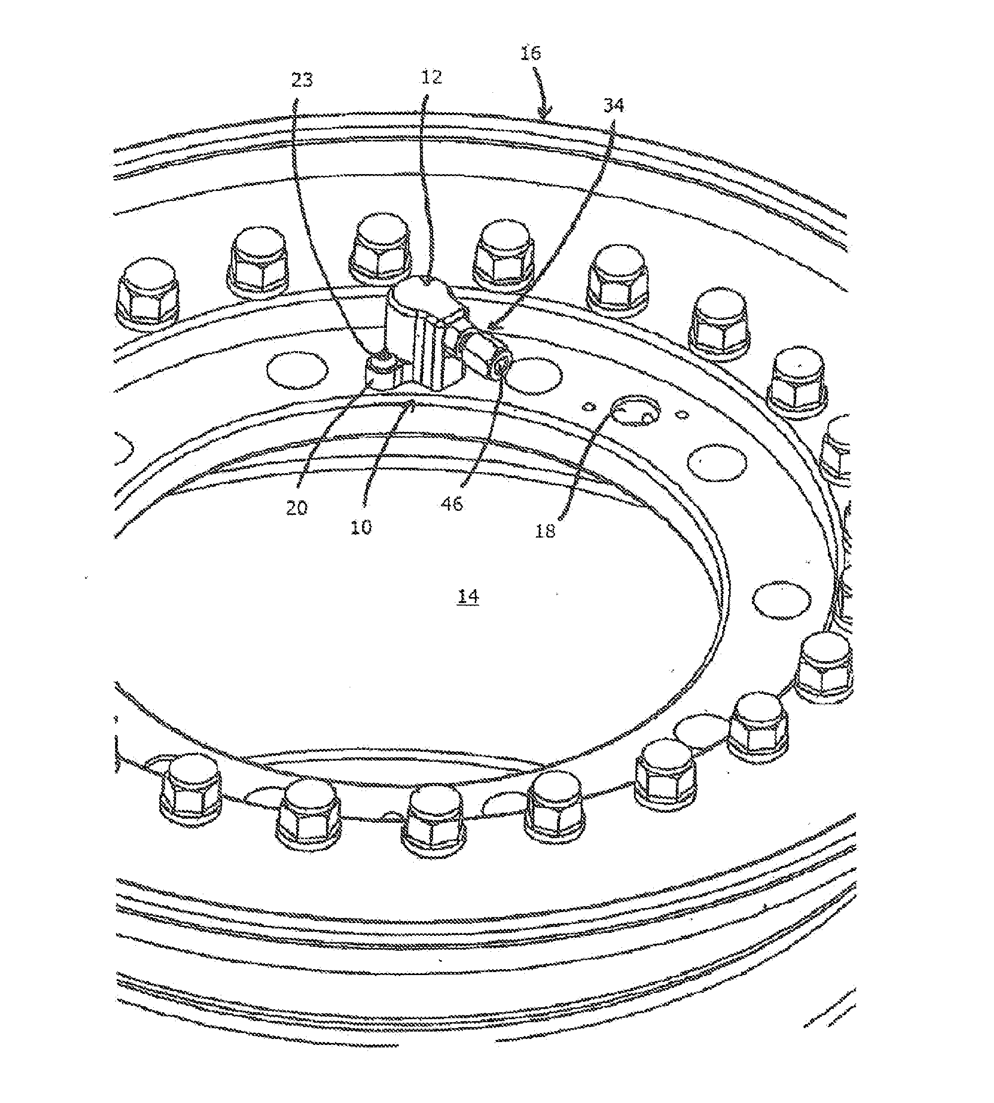
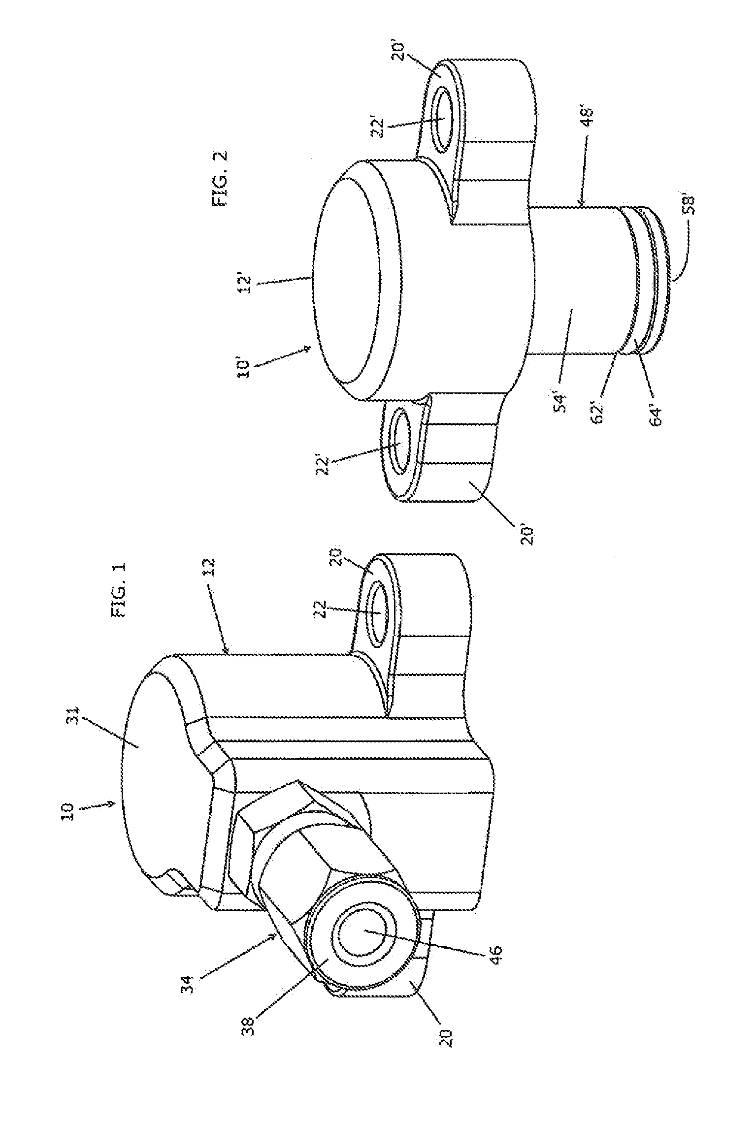
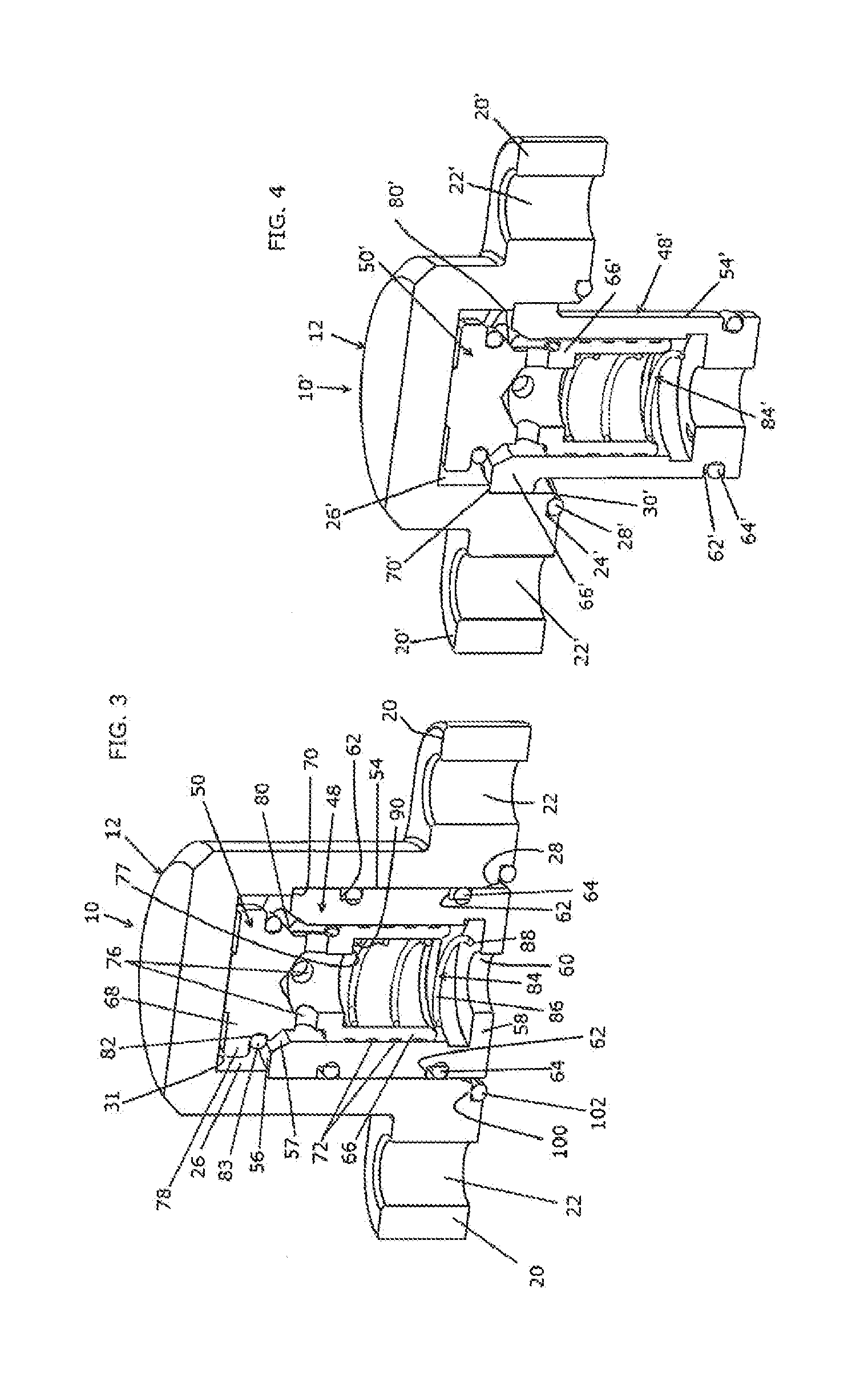
[0048]With reference now to the drawing figures in which like reference numerals designate like parts throughout the disclosure, a wheel valve constructed according to the present invention is indicted at 10 in FIGS. 1, 3 and 5-7. The valve 10 includes a casing 12 that is secured to the rim 14 of a wheel 16 adapted to support a tire (not shown) thereon. The rim 14 includes a number of air passages or channels 18 formed therein, with the casing 12 mounted over or otherwise in communication with one of the passages 18. The casing 12 is mounted flush against the rim 14 in any suitable manner to maintain an air-tight engagement between the casing 12 and the rim 14. In a preferred embodiment, the casing 12 includes a pair of flanges 20 extending outwardly from the casing 12 that include bores 22 formed therein. The bores 22 receive suitable fasteners 23 therethrough that are engaged with the rim 14 to affix the casing 12 to the rim 14. In a preferred embodiment, the flanges 20 are integr...

second embodiment

[0058]Looking now at FIGS. 2, 4, and 8-11, the valve 10′ is illustrated. In this embodiment, the valve 10′, instead of being mounted flush with the rim 14, as for valve 10, is mounted within the passage 18, such that the valve 10′ is recessed within the rim 14 to lessen exposed portion of the valve 10′ relative to the valve 10, and consequently reduce the potential for objects striking and damaging the valve 10′. The passage 18 is formed within a rim 14 having an inner rim 201 and is connected to an air channel 200 formed in the inner rim 201 in any suitable manner, such as by drilling, though the rim 14 to the passage 18, and channel 200 could also be formed in the outer rim 206, or between the outer rim 206 and the inner rim 201, if necessary. The channel 200 terminates in a groove 202 formed in a peripheral wall 204 of the inner rim 201, and that preferably extends radially inwardly from the channel 200 towards the center of the peripheral wall 204 of the inner rim 201. When an o...

third embodiment

[0077]Looking now at FIGS. 23-26, the manifold 700 is illustrated. The manifold 700 for each tire 1006 operably connected thereto includes a PO check valve assembly 7001, a PO check seat 701, a PO check activation piston 702, a pilot pressure port 703, a pressure sensor 704, a control circuit board 705, a control box housing 706, a check valve 707, and exhaust passage 708 to the valve 707, a connection 709 to the wheel valve 10, 10′, a secondary exhaust orifice 710, a primary exhaust orifice 711, a pressurized air passage 712 connected to the compressed air source 1002, a solenoid valve 713, and a PO check exhaust passage 714. The manifold 700 also includes a compressor inlet 715 that connects to each pressure passage 712, a PO check exhaust port 716, an exhaust valve 717 and a POC valve 718.

[0078]In FIG. 26 the system 1000 including the manifold 700 is schematically illustrated. The goal of the Independent CTIS 1000 is to allow for monitoring, inflating & deflating each tire 1006 i...


PUM


Abstract

The present invention is a valve for use in a central tire inflation system including a casing securable to the rim of a vehicle in communication with the tire that houses a main body connectable to a pressurized fluid supply of the central tire inflation system, and a valve member moveable within the main body to control the flow of air through the valve. The valve can be mounted flush on the exterior surface of the rim or in a recessed position within the rim, and can be connected to a manifold that is able to control the flow of pressurized fluid from the central tire inflation system to each valve and tire connected to the valve. The operation of the manifold and pressurized fluid supply can be controlled utilizing a controller operably connected to the manifold and fluid supply, and to sensing devices in the valve that supply information regarding the operational conditions of the vehicle to the controller to assist in adjusting the inflation of the tires as necessary.

Description

CROSS-REFERENCE TO RELATED APPLICATIONS[0001]This application claims priority as a continuation-in-part of U.S. Non-Provisional application Ser. No. 12 / 967,745, filed on Dec. 14, 2010, which in turn claims priority from U.S. Provisional Application Ser. No. 61 / 286,616, filed Dec. 15, 2009, and as a continuation-in-part of U.S. Non-Provisional application Ser. No. 12 / 568,805, filed on Sep. 29, 2009, which claims priority from U.S. Provisional Application Ser. No. 61 / 100,812, filed on Sep. 29, 2008, the entirety of which are each expressly incorporated by reference herein.FIELD OF THE INVENTION[0002]The present invention relates to tire inflation valves, and more specifically to a tire inflation valve that forms part of a central tire inflation system of a vehicle.BACKGROUND OF THE INVENTION[0003]In order to inflate and deflate the tires forming part of the wheels on a vehicle, valves are often located in or on the rims or hubs of the wheels to be used for selectively inflating and de...

Claims


Application Information

Patent Timeline
IPC IPC(8): B60C23/00
CPCB60C23/002B60C23/00318B60C23/00354B60C23/00363B60C23/00372Y10T137/3584
Inventor MEDLEY, MARTIN A.MILLER, DOUGLAS P.
Owner MEDLEY MARTIN A
Why Eureka
Try Eureka