Controllable energy store and method for operating a controllable energy store

a technology of controllable energy storage and energy storage device, which is applied in the direction of capacitor collector combination, parallel/serial switching, process and machine control, etc., can solve the problems of no longer being able to flow current through the battery, failure of the entire system, and failure of the entire energy storage device, so as to minimize the loss at the switch element

Active Publication Date: 2013-11-28
ROBERT BOSCH GMBH
View PDF10 Cites 4 Cited by
  • Summary
  • Abstract
  • Description
  • Claims
  • Application Information

AI Technical Summary

Benefits of technology

[0007]The invention is based on the fundamental idea of dividing each energy supply branch into two energy supply sub-branches that have in each case the reverse polarity of the allocated energy storage cells, in order in this manner to provide the option of reversing the voltage at the output of the energy storage module. In each case one of the energy supply sub-branches of the energy supply branch, namely the one with the “falsely polarized” energy storage cells, is disconnected in dependence upon a desired output voltage (positive or negative) of an energy supply branch. However, in contrast to the arrangement known from the prior art, it is not necessary that the coupling units are embodied as full bridges. On the contrary, the required function of the coupling units can also be achieved with a smaller number of controllable switch elements. This results in an operating current being carried by way of a smaller number of switch elements which in turn reduces the losses at the switch elements.
[0009]In accordance with a preferred embodiment of the invention, the coupling unit are embodied as half bridges, so that the operating current is carried in each case only by way of a switch element of the respective energy storage module. The losses at the switch elements are minimized in this manner.

Problems solved by technology

When connecting a plurality of cells in series, the problem arises in addition to a high total voltage that the entire energy storage device fails if a single battery cell fails because it is then no longer possible for the current to flow through the battery.
A failure of this type of the energy storage device can cause the entire system to fail.
In the case of a vehicle, a failure of the drive battery causes the vehicle “to be immobilized”.
In other applications, for example in the case of a rotor blade adjustment in wind turbines, situations that pose a safety risk can even occur in unfavorable boundary conditions, for example in the case of a strong wind.

Method used


Image

  • Controllable energy store and method for operating a controllable energy store
  • Controllable energy store and method for operating a controllable energy store

Examples


Embodiment Construction

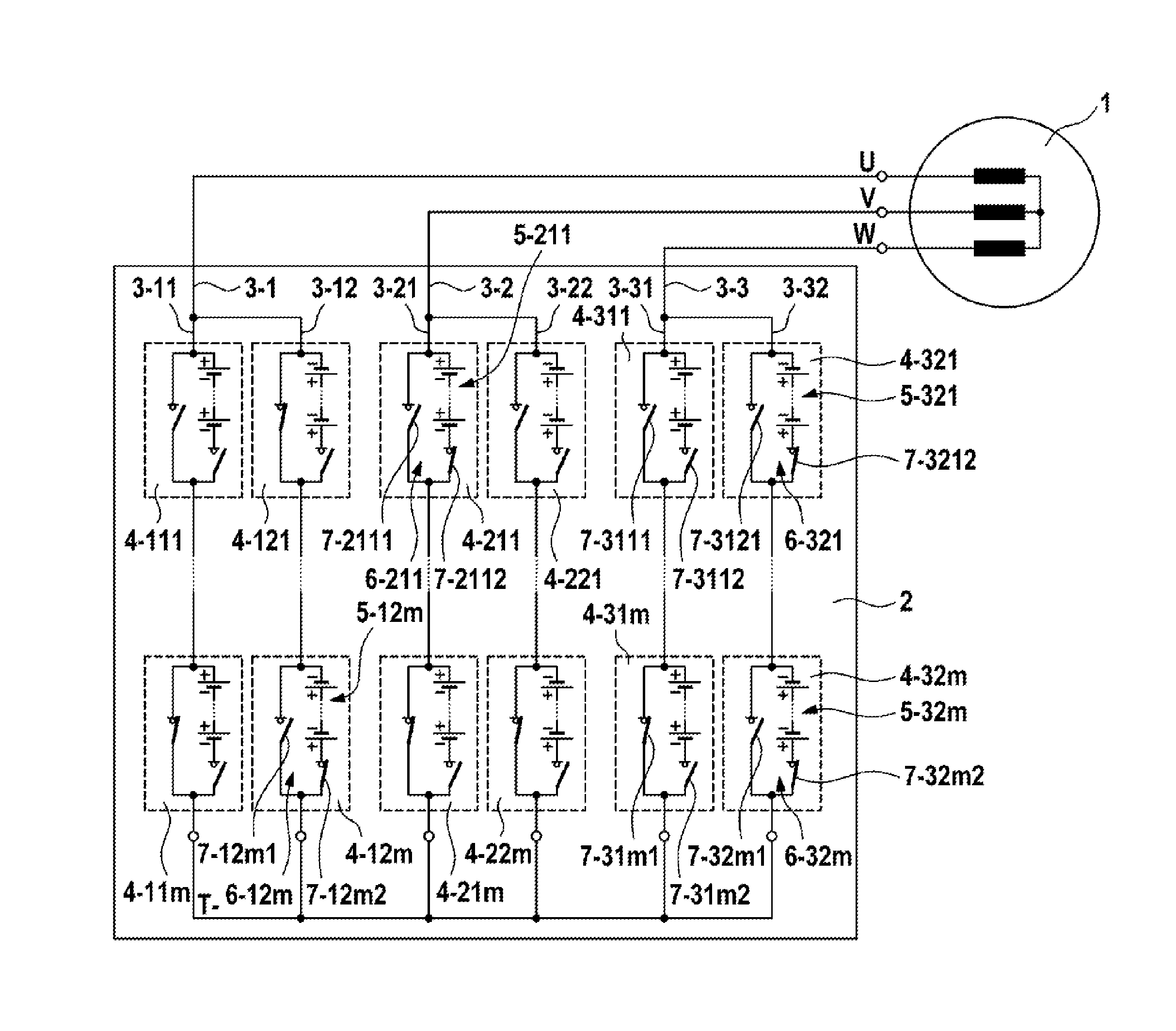
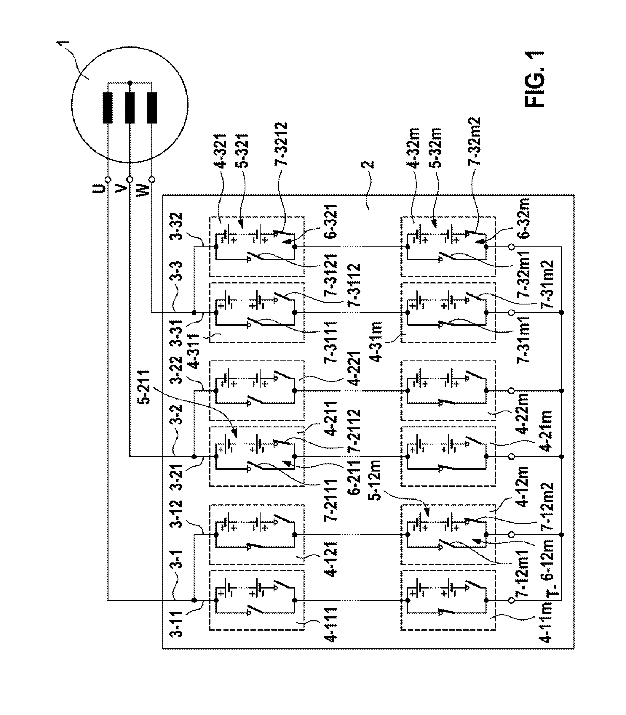
[0013]FIG. 1 shows a schematic illustration of a controllable energy storage device in accordance with the invention. A controllable energy storage device 2 is connected to a three-phase electrical machine 1. The controllable energy storage device 2 comprises three energy supply branches 3-1, 3-2 and 3-3 that are connected on the one side to a reference potential T-(reference rail) that in the illustrated embodiments is maintained at a low potential, and on the other hand are connected in each case to individual phases U, V, W of the electrical machine 1. The energy supply branches 3-1, 3-2 and 3-3 comprise in each case a first energy supply sub-branch 3-11 or respectively 3-21 or respectively 3-31 and a second energy supply sub-branch 3-12 or respectively 3-22 or respectively 3-32 that is connected in parallel to said first energy supply sub-branch. Each energy supply sub-branch 3-11, 3-12, 3-21, 3-22, 3-31, 3-32 comprises in each case m series-connected energy storage modules 4-11...


PUM


Abstract

The invention relates to a controllable energy store (2) with n parallel energy supply branches (3-1, 3-2, 3-3), wherein n≧1, each said branch having a first energy supply sub-branch (3-11; 3-21; 3-31) and a second energy supply sub-branch (3-12; 3-22;3-32) that is connected in parallel to said first energy supply sub-branch. Each energy supply sub-branch (3-11; 3-12; 3-21; 3-22; 3-31; 3-32) has at least one energy storing module (4), each of which comprises at least one electric energy storing cell (5) with a corresponding controllable coupling unit (6). The coupling units (6) disconnect the energy supply sub-branch (3-11; 3-12; 3-21; 3-22; 3-31; 3-32) or bridge the respective corresponding energy storing cells (5) or connect the respective corresponding energy storing cells (5) into the respective energy supply sub-branch (3-11; 3-12; 3-21; 3-22; 3-31; 3-32) dependent on control signals. The energy storing cells (5) of the energy storing modules (4) in the first energy supply sub-branch (3-11; 3-21; 3-31) and the energy storing cells (5) of the energy storing modules (4) in the second energy supply sub-branch (3-12; 3-22; 3-32) are arranged in an anti-parallel manner.

Description

BACKGROUND OF THE INVENTION[0001]The invention relates to a controllable energy storage device and a method for operating a controllable energy storage device.[0002]It has become apparent that in future both in the case of stationary applications, for example wind turbines, and also in vehicles, for example hybrid vehicles or electric vehicles, electronic systems are being used ever more frequently, which electronic systems combine new energy storage technologies with electrical drive technology. In conventional applications an electrical machine, which is embodied for example as a three-phase machine, is controlled by way of a converter in the form of an AC converter. A characterizing feature of systems of this type is a so-called DC voltage intermediate circuit, by means of which an energy storage device, generally a battery, is connected to the DC voltage side of the AC converter. In order to be able to fulfill the particular requirements relating to power and energy for a partic...

Claims


Application Information

Patent Timeline
Patent Type & Authority Applications(United States)
IPC IPC(8): H02J4/00
CPCH02J4/00H01G9/26H01G11/08H01G11/72H01M10/441H02J7/0013H02J7/0024H02J7/1492B60L15/007Y02T90/14Y02T10/92Y02T10/7072B60L53/22B60L53/24B60L58/19B60L50/64H02J2207/20H02J2310/48H02J2300/28H02J7/0025Y02T10/70Y02T10/64Y02E60/10H01M10/44H01G9/00H02J7/00Y02E60/13Y02E10/76Y02T90/12
Inventor FEUERSTACK, PETERWEISSENBORN, ERIKKESSLER, MARTIN
Owner ROBERT BOSCH GMBH
Why Eureka
Try Eureka