Ultrasonic head trap

Inactive Publication Date: 2013-12-12
ACCESS BUSINESS GRP INT LLC
View PDF3 Cites 0 Cited by
  • Summary
  • Abstract
  • Description
  • Claims
  • Application Information

AI Technical Summary

Benefits of technology

[0005]Accordingly, the present invention overcomes and/or reduces the disadvantages of bubbles associated with ultrasonic heat energy delivery systems. According to one aspect, one or more bubble traps are provided that capture, maintain, and/or assist in keeping bubbles in one or more locations outside of the direct ultrasonic energy transmission path through the fluid, thereby reducing or eliminating any interference the bubbles would otherwise create with the transmission of ultrasonic energy through the fluid. In other aspects, an ultrasonic energy delivering wand is provid

Problems solved by technology

Such bubbles tend to interfere with the transmission of ultrasonic energy from the transducer to the target, decreasing the efficiency of the transfer and/or changing the focusing of the

Method used


Image

  • Ultrasonic head trap
  • Ultrasonic head trap
  • Ultrasonic head trap

Examples


Embodiment Construction

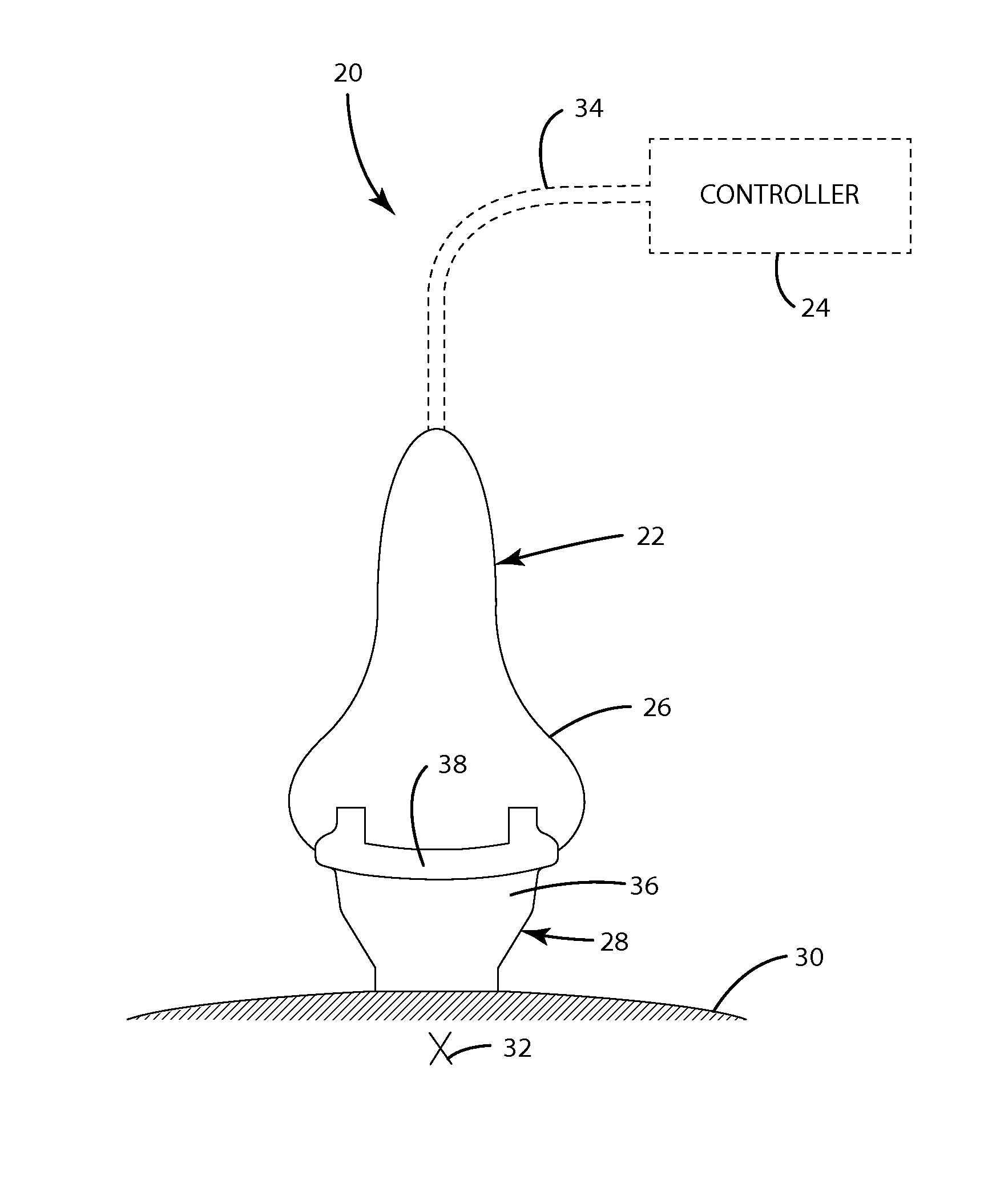
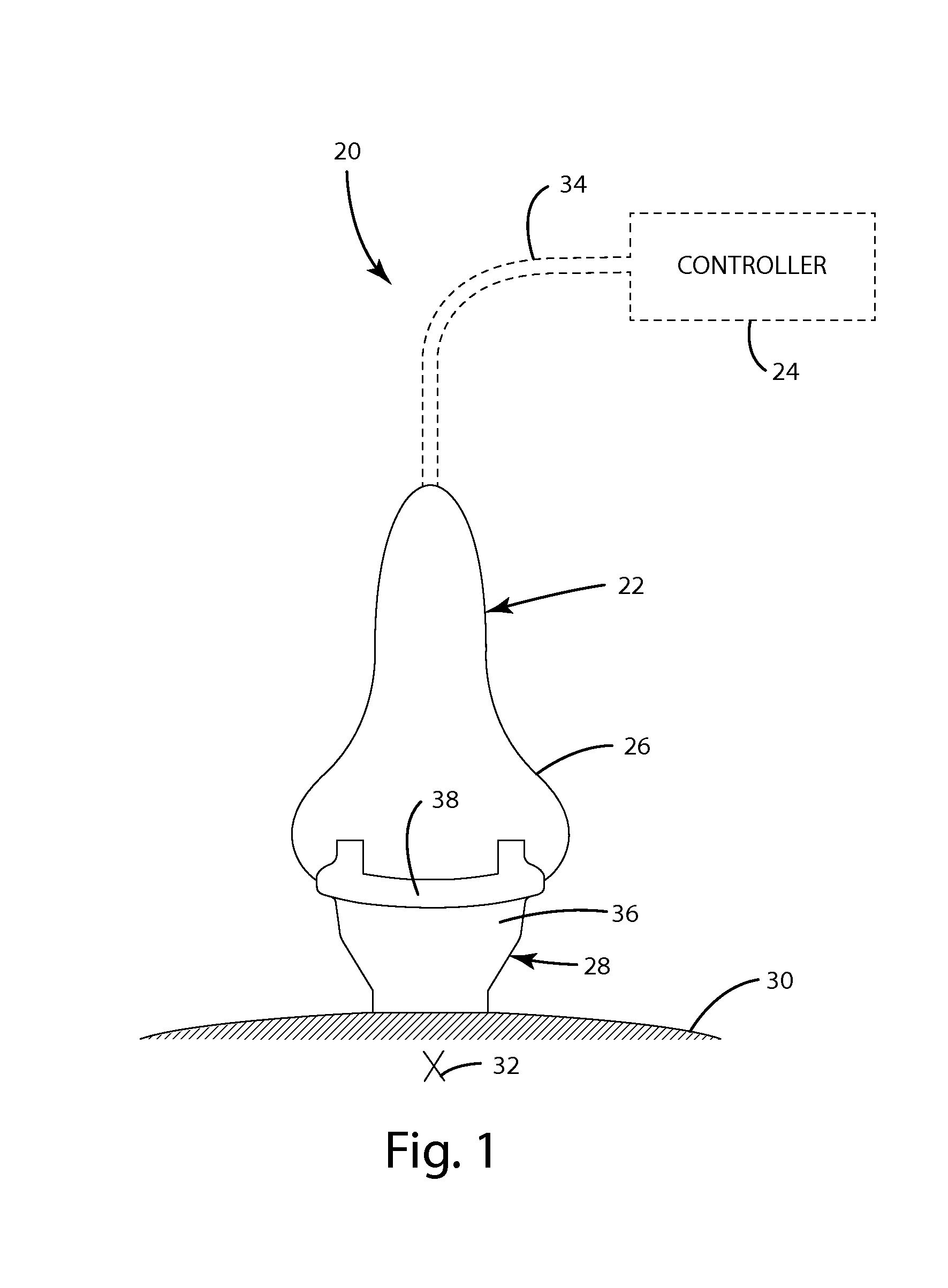
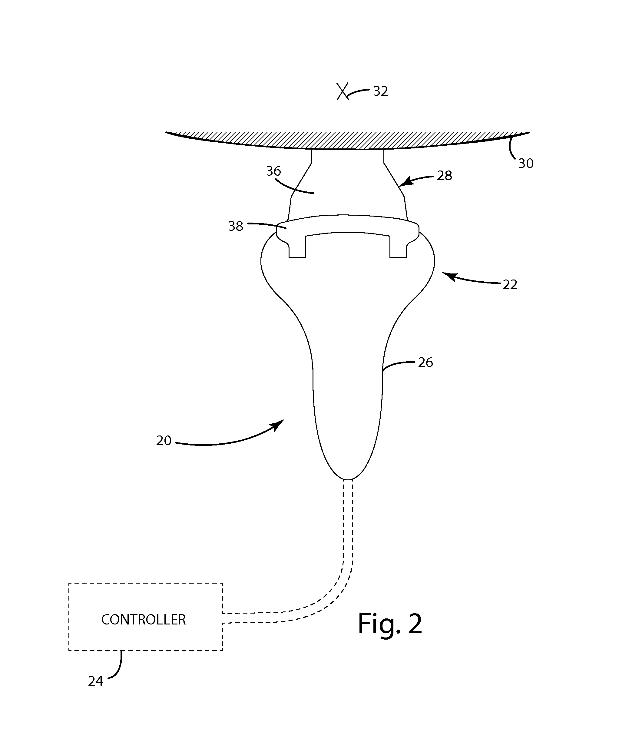
[0031]An ultrasonic delivery system 20 according to one embodiment is shown in FIG. 1. Ultrasonic delivery system 20 includes an ultrasonic wand 22 and an external controller 24. Wand 22 includes an ultrasonic transducer 26 and an ultrasonic module 28. Wand 22 is adapted to be applied to the skin 30 of a patient in order to deliver ultrasonic energy to a target area 32. The delivery of the ultrasonic energy to the target area 32 is adapted to generate heat, and, in some embodiments, the delivery of heat is useful for cosmetic purposes. It will, however, be understood by those skilled in the art that the delivery of ultrasonic energy to target area 32 may be for any useful purpose, whether cosmetic or otherwise. It will further be understood by those skilled in the art that the position of the target area 32 may vary from that shown in FIGS. 1 and 2. That is, in some embodiments, target area 32 may be positioned internally under the skin 30, such as shown in FIGS. 1 and 2, while in o...


PUM


Abstract

A wand for delivering therapeutic ultrasonic energy to a target area includes a module and a transducer. The transducer converts electrical energy into ultrasonic vibrations that are delivered to the module. The module includes a fluid chamber that houses an ultrasonic fluid. In order to reduce or eliminate the deleterious effects of bubbles that may form in the ultrasonic fluid, one or more bubble traps are defined in the fluid chamber that capture, store, and/or assist in keeping the bubbles outside of the direct transmission path of the ultrasonic energy through the fluid. One or more barriers may be included in the trap(s) that obstruct movement of the bubbles into the transmission path when the wand is tilted to different orientations. After passing through the fluid, the ultrasonic energy is delivered to the skin of a patient, or other surface to which the ultrasonic energy is being directed.

Description

CROSS-REFERENCE TO RELATED APPLICATIONS[0001]This application claims priority to U.S. provisional patent application Ser. No. 61 / 657,316 filed Jun. 8, 2012 by Bradley J. Pippel and entitled Ultrasonic Head Trap, the complete disclosure of which is hereby incorporated herein by reference.BACKGROUND OF THE INVENTION[0002]The present invention relates to ultrasonic devices, and more particularly to ultrasonic devices adapted to deliver heat energy to one or more targeted locations.[0003]Ultrasonic energy may be used to deliver heat energy to a target by focusing the ultrasonic vibrations such that they arrive at the target in a concentrated manner. Such techniques may be useful for delivering ultrasound treatments to human or other animal tissue, particularly treatments intended to treat fatty tissues underlying the skin for cosmetic reasons. Systems for delivering ultrasonic energy to mammalian tissue in order to heat the tissue typically include an ultrasonic transducer, a control sy...

Claims


Application Information

Patent Timeline
IPC IPC(8): A61N7/02
CPCA61N7/02A61N2007/0008A61N2007/0034G10K11/02
Inventor PIPPEL, BRADLEY J.BYLSMA, RICHARD B.
Owner ACCESS BUSINESS GRP INT LLC
Why Eureka
Try Eureka