Lighting system using dispersed fluorescence

Inactive Publication Date: 2014-12-11
Q TECH CO LTD
View PDF5 Cites 0 Cited by
  • Summary
  • Abstract
  • Description
  • Claims
  • Application Information

AI Technical Summary

Benefits of technology

[0006]The use of dispersed fluorescence as part of the present invention overcomes the problems associated with prior art. In a compact space not bigger than an incandescent bulb, a large light output is possible with even light distribution, thus reducing the disadvantages of other LED designs requiring large optics and heat sink.
[0007]The present invention is made of a blue or shorter wavelength (possibly ultraviolet) source and fluorescent material dispersed in a liquid or solid. Additional benefits are that under some choices of materials the light output is uniform enough to look at directly.
[0008]In a preferred embodiment, a liquid medium supporting the fluorescent material also allows for efficient LED heat removal. In effect, the liquid with dispersed fluorescence serves two purposes: first, to produce a uniform illumination pattern, and secon

Problems solved by technology

At times users find that incandescent lamps consume excessive energy and radiate excessive heat.
On the other hand gas discharge fluorescent lamps often use mercury and present disposal issues.
In summary, these technologies have complementary issues concerning energy consumption, toxic waste

Method used


Image

  • Lighting system using dispersed fluorescence
  • Lighting system using dispersed fluorescence
  • Lighting system using dispersed fluorescence

Examples


Example

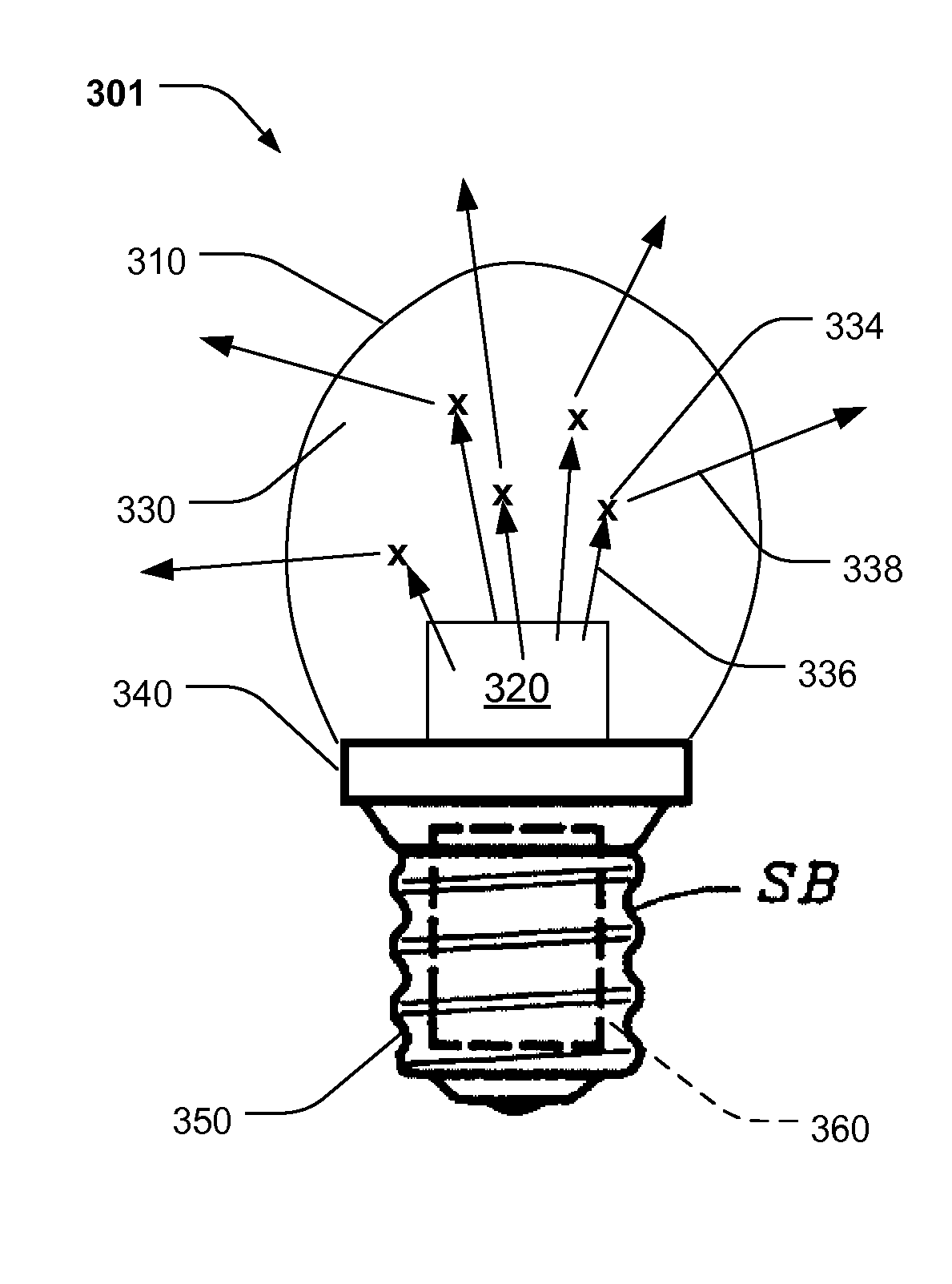
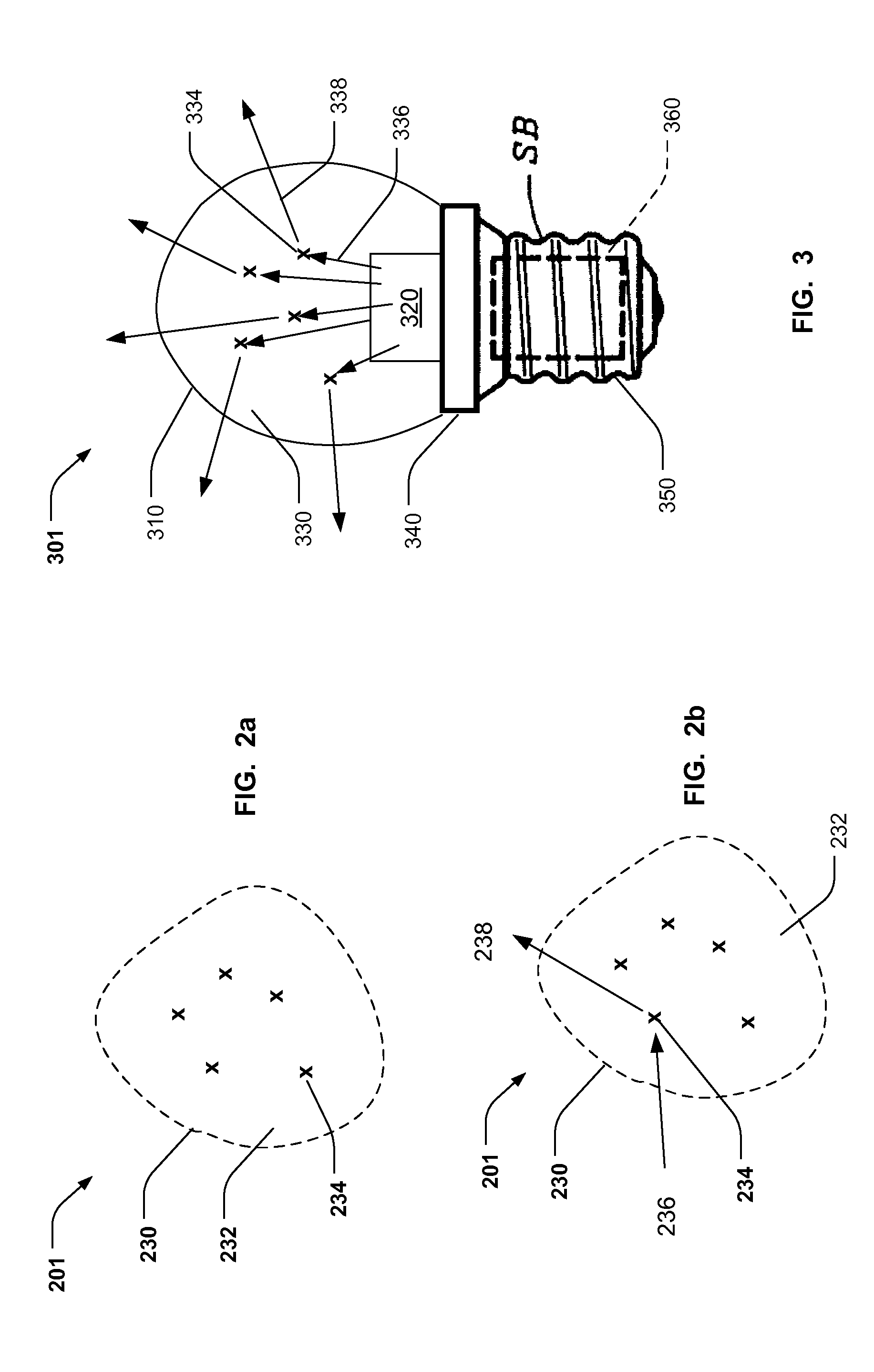
[0015]In FIG. 1, an embodiment of the present invention 101 consists of a light transmissive envelope 110 with excitation light source 120. A light re-emitting medium 130 exists between the excitation light source 120 and the envelope 110. A base 140 is shown to portray connection to electrical supply and mechanical support, and may be of type well known in the art. Optionally, circuitry to modify the electricity applied through the base 150 and sent to the source 120 may be at least partially enclosed within the socket as for example, the region shown in dashed box 160.

[0016]The excitation light source 120 may be a blue or shorter wavelength source as known to the art. The chemistry of the material may, for example, be InGaN (indium gallium nitride), or that used in a standard white LED known to the art.

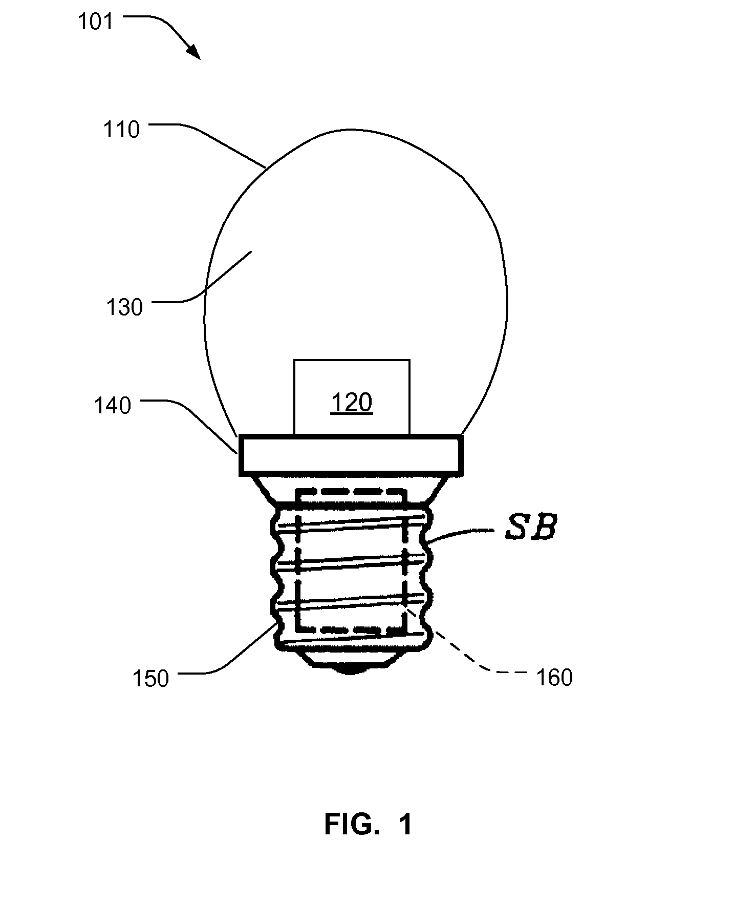
[0017]FIG. 2a shows detail of a light re-emitting medium 201, corresponding to medium 130 in FIG. 1. The medium 201 is composed of fluorescent material 234 suspended in the suspensi...


PUM


Abstract

A system for generating light using a blue or ultraviolet light emitter as excitation source for dispersed fluorescent material is disclosed. A light transmissive dispersant, which may colloidally suspend or chemically dissolve a fluorescent material, acts to distribute the fluorescent material over a spatial region. The combination of primary and secondary light emission results in a broader light spectrum than the primary emitter alone would produce. Extending the light transmissive dispersant medium containing fluorescent material over a spatial region spanning beyond point sources will minimize or eliminate bright spots, which might otherwise result from point sources. Use of a liquid dispersant may result in convective cooling of the emission sources.

Description

REFERENCE TO RELATED APPLICATIONS[0001]This patent application claims the benefit of priority under 35 USC sections 119 and 120 of a provisional patent application filed Jun. 10, 2013 having Application Ser. No. 61 / 833,415. The entirety of the said U.S. provisional application 61 / 833,415, entitled “Lighting System Using Dispersed Fluorescence”, is incorporated by reference herein.BACKGROUND OF THE INVENTION[0002]The present invention relates generally to lighting systems and methods and more specifically to lighting sources using fluorescence.DESCRIPTION OF RELATED ART[0003]Incandescent, gaseous discharge fluorescent, and LED lamps are commonly used to illuminate living and working spaces. At times users find that incandescent lamps consume excessive energy and radiate excessive heat. On the other hand gas discharge fluorescent lamps often use mercury and present disposal issues. Still yet, LEDs tend to be directional point sources and so require additional optics to produce uniform...

Claims


Application Information

Patent Timeline
IPC IPC(8): F21K99/00C09K11/02F21V29/00
CPCF21K9/56C09K11/025F21V29/30F21V3/00F21V29/58F21K9/232F21K9/64F21Y2115/10C09K11/08
Inventor STACK, THOMAS E.
Owner Q TECH CO LTD
Why Eureka
Try Eureka