

Tube bundle-type heat exchanger, tube base, and method for sealing same
- Summary
- Abstract
- Description
- Claims
- Application Information
AI Technical Summary
Benefits of technology
Problems solved by technology
Method used
Image

Examples
Embodiment Construction
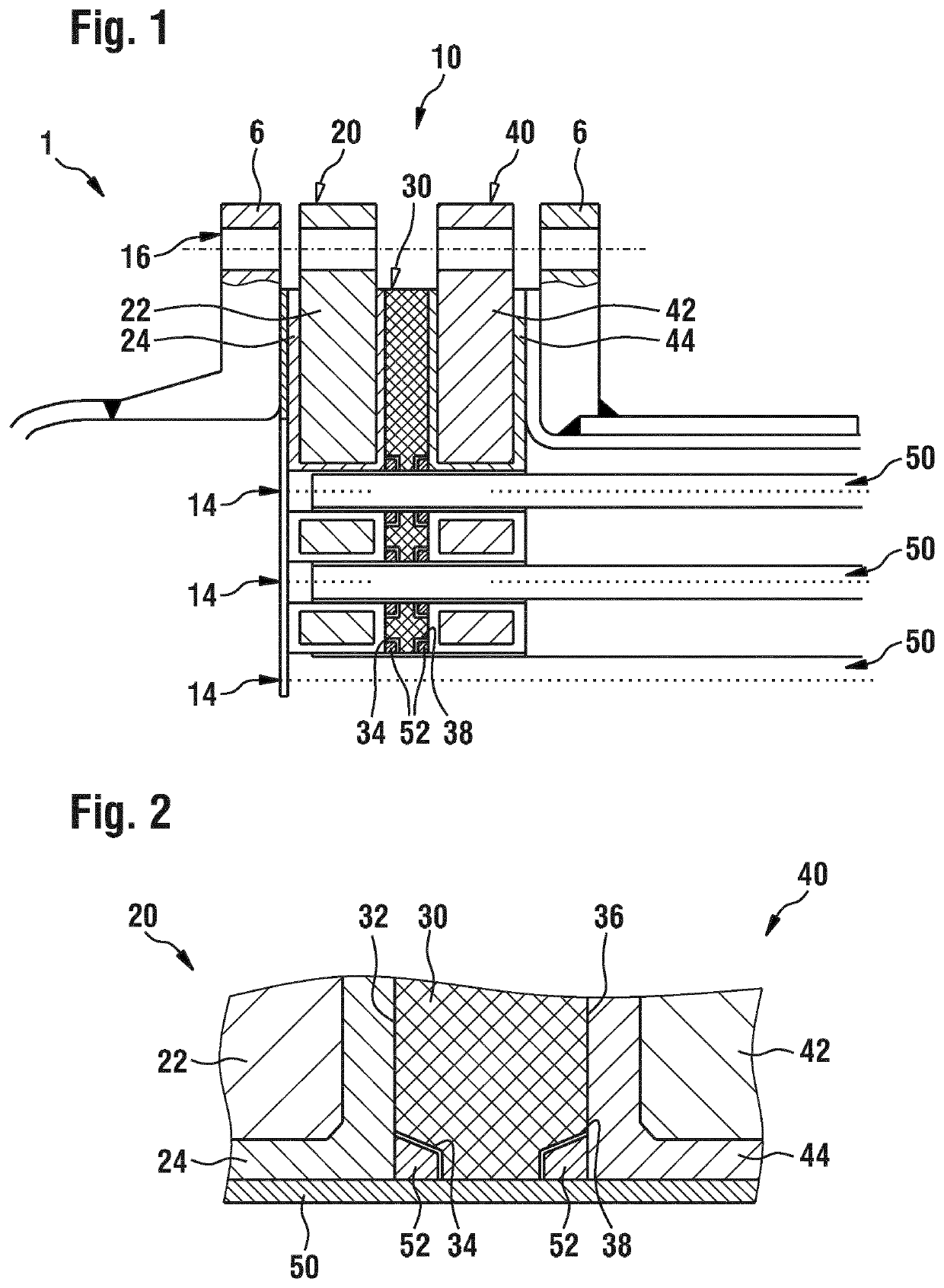
lass="d_n">[0038]With reference to FIG. 1, a shell-and-tube heat exchanger 1 according to one embodiment of the invention is described below. The shell-and-tube heat exchanger 1 has a housing 6, a tube base 10 with through-openings 14, and tubes 50 which pass through the respective through-openings 14.
[0039]In operation, the tubes 50 contain a first fluid and are surrounded by a second fluid located in an inner housing region (to the right of the tube base 10 in FIG. 1), so that a heat exchange between the first and the second fluid can take place through the tube walls. The entry and exit points of the tubes 50 (to the left-hand side of the tube base 10 in FIG. 1) are separated by the tube base 10 from the inner housing region to the right of the tube base 10 and are sealed therein as described below.
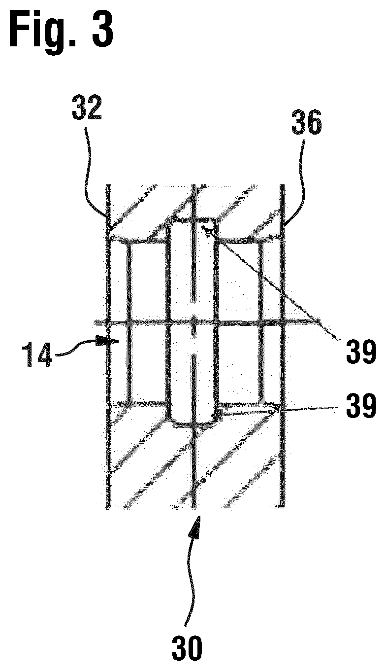
[0040]The tube base 10 comprises a first tube base plate 20 with a core 22 and plastics sheathing 24 surrounding the core, a second tube base plate 30 made of the temperature-resistant...
PUM
| Property | Measurement | Unit |
|---|---|---|
| Temperature | aaaaa | aaaaa |
| Temperature | aaaaa | aaaaa |
Abstract
Description
Claims
Application Information