Electrostatic induction generation device and electrostatic induction generation apparatus having a movable electrode formed between a first fixed electrode substrate and a second fixed electrode substrate

Inactive Publication Date: 2014-01-16
SEIKO EPSON CORP
View PDF4 Cites 2 Cited by
  • Summary
  • Abstract
  • Description
  • Claims
  • Application Information

AI Technical Summary

Benefits of technology

[0019]According to this application example of the invention, the electrostatic induction generation apparatus capable of efficie

Problems solved by technology

In the electrical power generation using the electrostatic method, the charge held by the electret and the dielectric charge generated on the opposed electrode cause the Coulomb force in the attracting direction to act between electrodes to thereby make the electrodes opposed to each other with a small gap have contact with each other, which hinders the relative displacement o

Method used


Image

  • Electrostatic induction generation device and electrostatic induction generation apparatus having a movable electrode formed between a first fixed electrode substrate and a second fixed electrode substrate
  • Electrostatic induction generation device and electrostatic induction generation apparatus having a movable electrode formed between a first fixed electrode substrate and a second fixed electrode substrate
  • Electrostatic induction generation device and electrostatic induction generation apparatus having a movable electrode formed between a first fixed electrode substrate and a second fixed electrode substrate

Examples


Example

First Embodiment

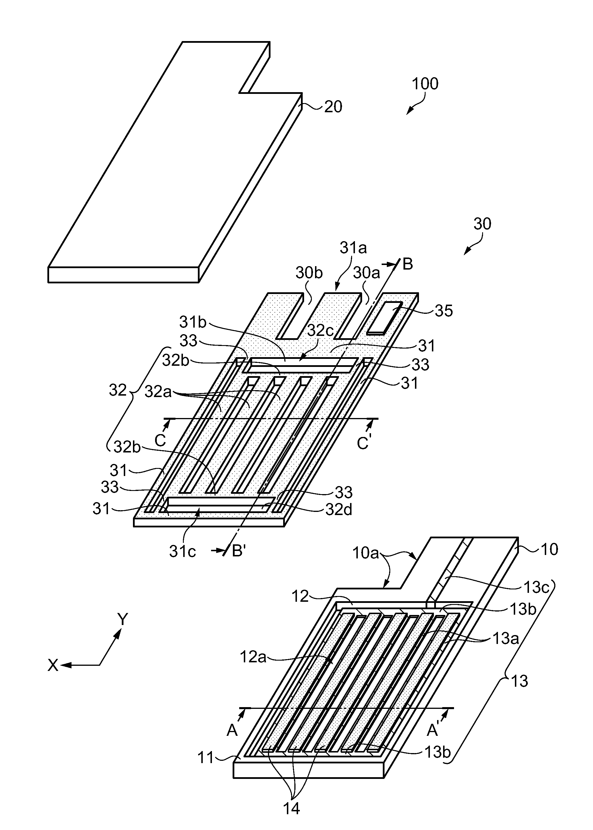
[0031]FIG. 1 is an external perspective view showing the electrostatic induction generation device according to the present embodiment. The electrostatic induction generation device 100 shown in FIG. 1 is composed of a first substrate 10 as a first fixed electrode substrate provided with an electret on the fixed electrode described later, a movable substrate 30 provided with a movable section, and a second substrate 20 as a second fixed electrode substrate provided with the electret on the fixed electrode, stacked so that the first substrate 10 and the second substrate 20 sandwich the movable substrate 30.

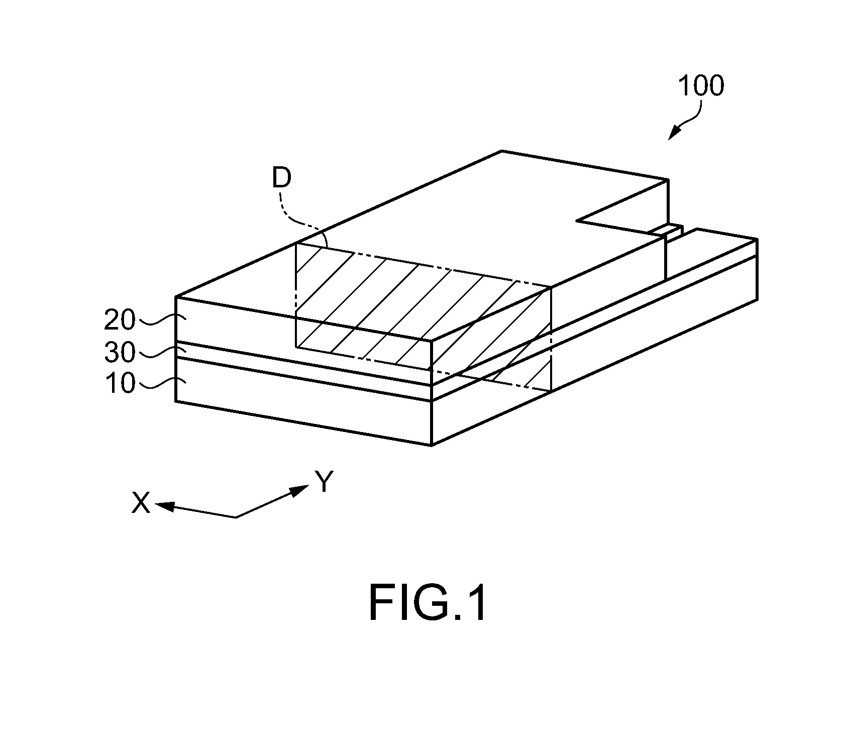
[0032]FIG. 2 is an external perspective view of the electrostatic induction generation device 100 shown in FIG. 1 in an exploded state. The first substrate 10 is a glass substrate, and borosilicate glass, for example, is preferably used therefor. One surface 11 (hereinafter referred to as an electrode forming surface 11) of the first substrate 10 is provided with a ...

Example

[0052]A second embodiment of the invention is shown in FIG. 8. Similarly to the first embodiment, the electrostatic induction generation device 200 shown in FIG. 8 is provided with a movable substrate 230, and a first substrate 210 and a second substrate 220 disposed so as to sandwich the movable substrate 230. The movable substrate 230 has a movable electrode holding frame 231 formed along the outer shape thereof to have a frame shape. A movable electrode 232A and a movable electrode 232B are coupled to the movable electrode holding frame 231 via electrode support beams 233a, 233b. The extending directions of the movable electrode fingers 232a, 232b provided to the respective movable electrodes 232A, 232B are perpendicular to each other. Specifically, in the drawing, the movable electrode fingers 232a are formed so as to extend in the Y direction, and the movable electrode fingers 232b are formed so as to extend in the X direction.

[0053]The first substrate 210 used for sandwiching ...

Example

Third Embodiment

[0057]As a third embodiment of the invention, an electrostatic induction generation apparatus using the electrostatic induction generation device according to the first embodiment will be explained. FIG. 9 is a block diagram showing the electrostatic induction generation apparatus 1000 according to the third embodiment of the invention. The electrostatic induction generation apparatus 1000 is provided with the electrostatic induction generation device 100, a power control section 300, and a charging section 400, and supplies the drive device 500 to be a drive object with the electricity thus generated.

[0058]The electricity generated by the electrostatic induction generation device 100 is taken out as an irregular current. The power control section 300 converts the irregular current into stable electricity, and then supplies the drive device 500 with the electricity. Further, if the supply of the electricity to the drive device 500 is not required, the power control s...


PUM


Abstract

An electrostatic induction generation device comprising a first fixed electrode substrate having a first electret electrode, a second fixed electrode substrate having a second electret electrode, a movable electrode substrate having a movable electrode, a holding frame formed separately from the movable electrode, a first pair of electrode support beams and a second pair of electrode support beams connected with the movable electrode and the holding frame, and wherein the movable electrode substrate is formed between the first fixed electrode substrate and the second fixed electrode substrate, and the movable electrode is opposed to the first electret electrode and the second electret electrode.

Description

CROSS-REFERENCE TO RELATED APPLICATIONS[0001]This is a continuation application of U.S. patent application Ser. No. 13 / 214,538 filed Aug. 22, 2011 which claims priority to Japanese Patent Application No. 2010-185854 filed Aug. 23, 2010 all of which are expressly incorporated by reference herein in their entireties.BACKGROUND[0002]1. Technical Field[0003]The present invention relates to an electrostatic induction generation device and an electrostatic induction generation apparatus.[0004]2. Related Art[0005]In accordance with the recent environmental concerns, electrical power generation using natural energy such as electrical power generation using solar energy or wind energy has been starting to spread widely. However, both of the solar energy and the wind energy must depend on the conditions for installation, namely the environment such that the sunlight is not blocked or that the stable wind is blowing. In contrast thereto, a method of converting the environmental vibration into ...

Claims


Application Information

Patent Timeline
IPC IPC(8): H02N1/08
CPCH02N1/08
Inventor SANO, AKIRA
Owner SEIKO EPSON CORP
Why Eureka
Try Eureka