Display device and electronic apparatus
a technology of electronic equipment and display device, which is applied in the direction of instruments, computing, electric digital data processing, etc., can solve the problems of device generation, streak defects or unevenness of images
- Summary
- Abstract
- Description
- Claims
- Application Information
AI Technical Summary
Benefits of technology
Problems solved by technology
Method used
Image
Examples
embodiment
1. Embodiment
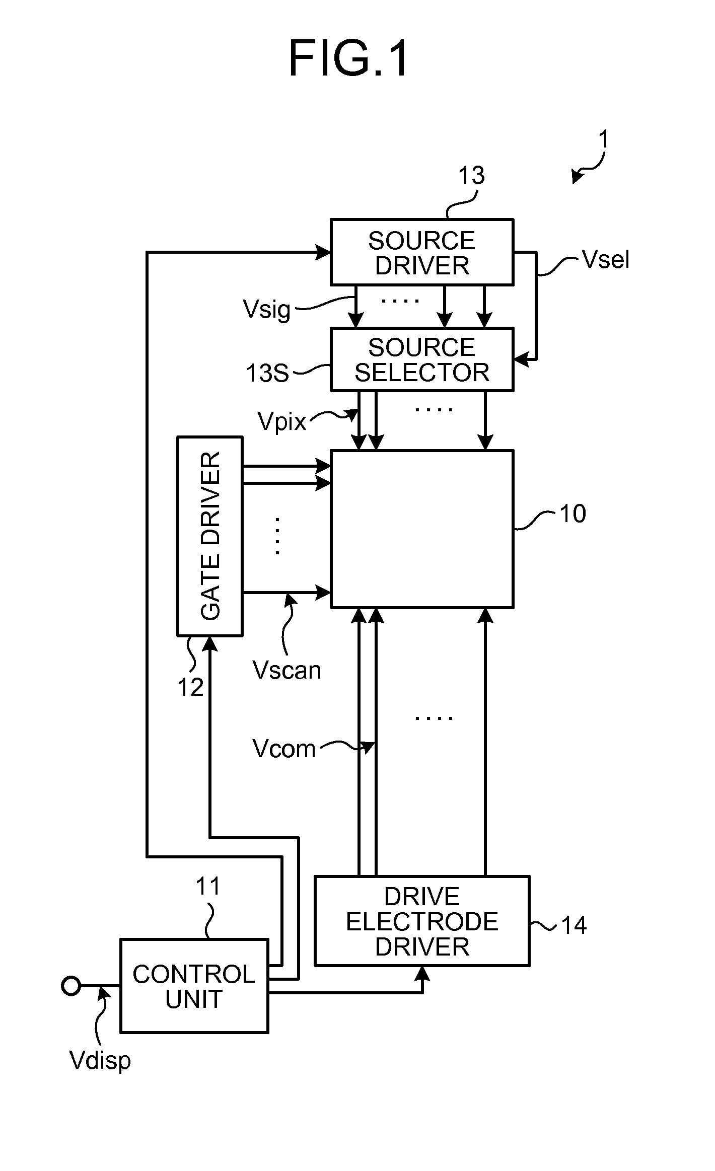
[0057]A liquid crystal display device to which the present disclosure is applied may be a display device for monochrome display or a display device for color display. In a display device for color display, one pixel (unit pixel) serving as a unit of forming a color image includes a plurality of sub-pixels. More specifically, the unit pixel in the display device for color display includes, for example, a total of three sub-pixels of a sub-pixel displaying red (R), a sub-pixel displaying green (G), and a sub-pixel displaying blue (B).
[0058]However, one pixel is not limited to the combination of the sub-pixels of the three primary colors of R, G, and B. The unit pixel can be formed, for example, by adding a sub-pixel of one color or sub-pixels of a plurality of colors to the sub-pixels of the three primary colors of R, G, and B. More specifically, the unit pixel can be formed, for example, by adding a sub-pixel displaying white (W) to increase luminance, or by adding at le...
application examples
2. Application Examples
[0149]With reference to FIGS. 26 to 38, a description will be made of application examples of the display device 1 described in the embodiment and the modifications thereof. FIGS. 26 to 38 are diagrams each illustrating an example of an electronic apparatus to which the display device according to the present embodiment or any of the modifications thereof is applied. The display device 1 according to the present embodiment or the display device according to any of the modifications thereof can be applied to electronic apparatuses in all fields, such as television devices, digital cameras, laptop computers, portable electronic apparatuses including mobile phones, and video cameras. In other words, the display device 1 according to the present embodiment or the display device according to any of the modifications thereof can be applied to electronic apparatuses in all fields that display externally received video signals or internally generated video signals as ...
application example 1
[0150]The electronic apparatus illustrated in FIG. 26 is a television device to which the display device 1 according to the present embodiment or the display device according to any of the modifications thereof is applied. This television device includes, for example, a video display screen unit 510 that includes a front panel 511 and a filter glass 512. The video display screen unit 510 corresponds to the display device 1 according to the present embodiment or the display device according to any of the modifications thereof.
PUM
 Abstract
Description
Claims
Application Information
 - R&D Engineer
- R&D Manager
- IP Professional
- Industry Leading Data Capabilities
- Powerful AI technology
- Patent DNA Extraction
Browse by: Latest US Patents, China's latest patents, Technical Efficacy Thesaurus, Application Domain, Technology Topic.
© 2024 PatSnap. All rights reserved.Legal|Privacy policy|Modern Slavery Act Transparency Statement|Sitemap


