Lighting dimmer synchronous load device

a technology of synchronous load and dimmer, which is applied in the direction of discharge tube/lamp details, electric discharge lamps, semiconductor lamp usage, etc., can solve the problems of reducing the input voltage of the driver, affecting the operation of the driver and the dimmer, and unfavorable interference, etc., to achieve effective and efficient solutions.

Active Publication Date: 2014-10-23
MAGNITUDE HLDG LTD A BERMUDA EXEMPT COMPANY LIMITED BY SHARES
View PDF6 Cites 3 Cited by
  • Summary
  • Abstract
  • Description
  • Claims
  • Application Information

AI Technical Summary

Benefits of technology

[0005]Accordingly, it is a principal object of the present invention to provide an effective and efficient solution to the interference phenomena arising when connecting a lighting driver, typically a LED driver, to a traditional, typically triac-based, external dimmer, in particular an electronic external dimmer.

Problems solved by technology

In this case undesirable interference might occur.
This interference would typically disrupt the operation of the driver and the dimmer.
Another problem arises, in the case of an external electronic dimmer, when the driver's input capacitance charges during the external dimmer's conducting period and prevents a voltage drop from developing on the external dimmer's control circuits during the dimmer cutoff period.
However, such a series resistor reduces the input voltage of the driver and is not effective enough for external electronic dimmer.
Connecting a resistor parallel to the driver input is also a known technique, however power wasteful.

Method used


Image

  • Lighting dimmer synchronous load device
  • Lighting dimmer synchronous load device
  • Lighting dimmer synchronous load device

Examples


Embodiment Construction

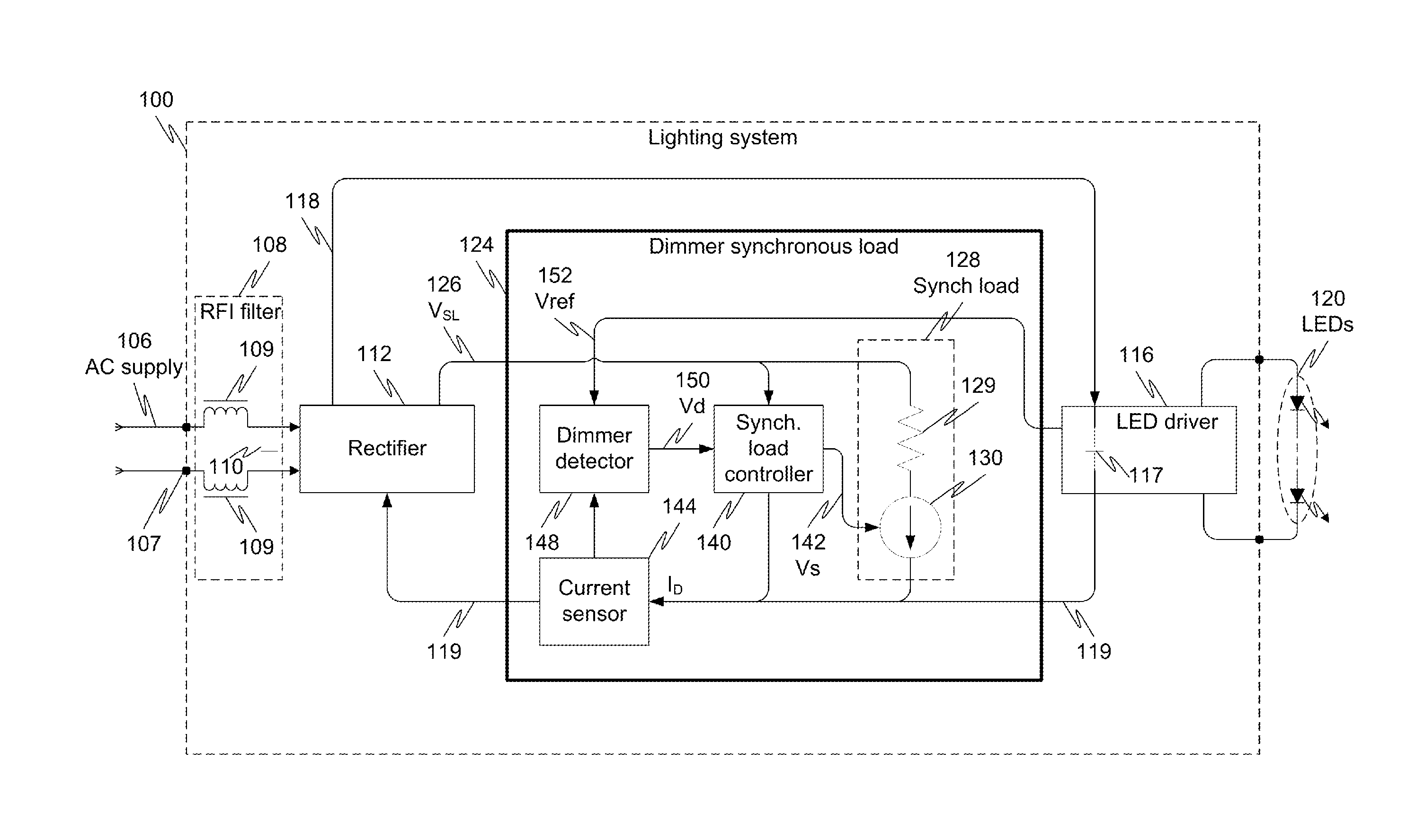
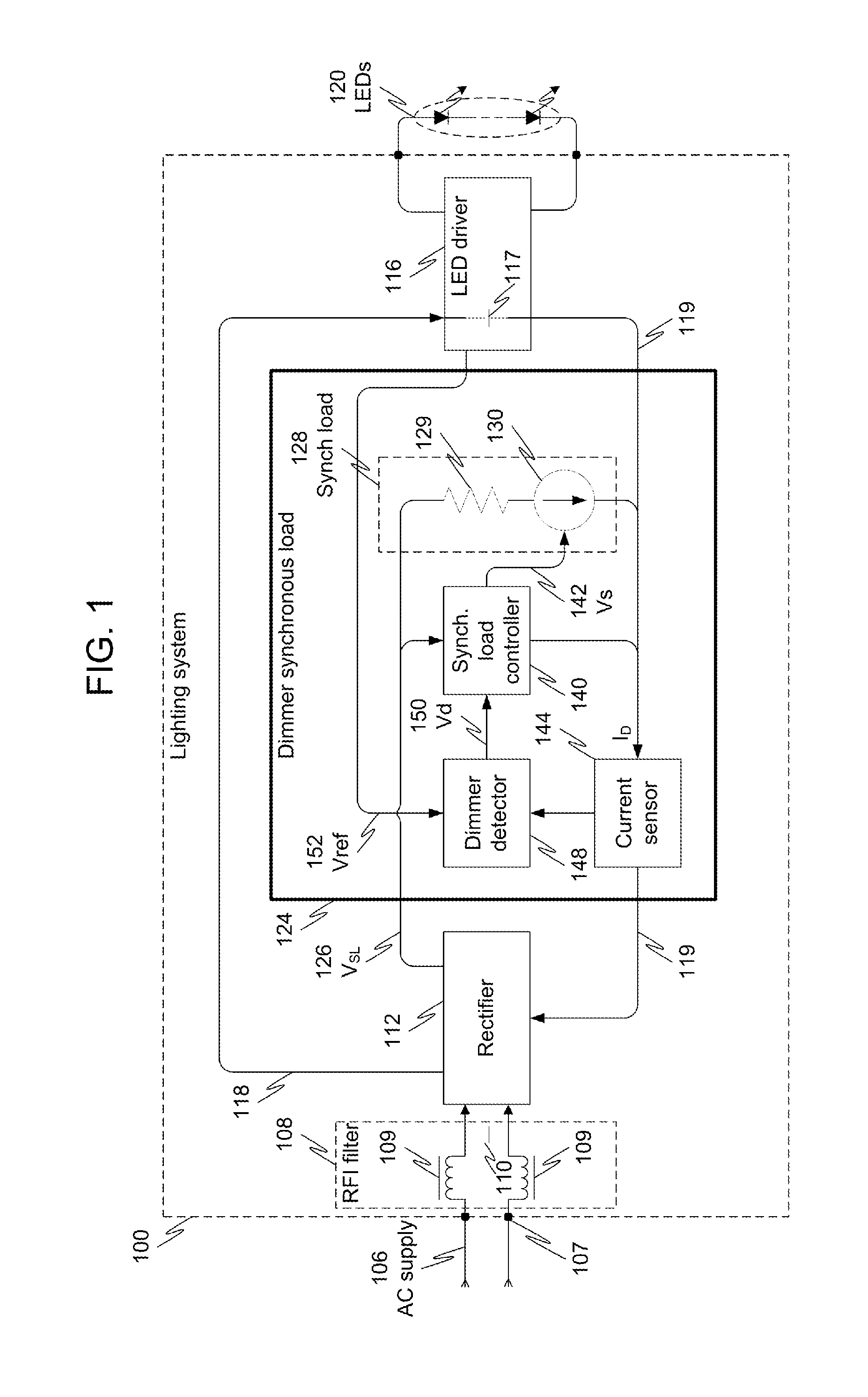
[0033]Embodiments of the present invention provide improved methods and systems for driving modern lighting means, typically LEDs, wherein the lighting driver is connected to an AC supply voltage that is potentially produced by a dimmer. In an embodiment, an efficient operation of both the lighting driver and the dimmer is achieved due to optimally loading the dimmer by a controllable synchronous load. In particular, the present invention discloses techniques for efficiently suppressing current oscillations that typically result when loading a dimmer by a LED driver, and ensuring a minimal loading that is needed for a proper operation of the dimmer.

[0034]Referring to FIG. 1 there is shown a block diagram that schematically illustrates a lighting system 100, in accordance with an embodiment of the present invention. Lighting system 100 is fed by an AC supply 106 which provides an AC supply voltage, denoted 106 as well, fed at an input port 107 of lighting system 100. Within lighting ...


PUM


Abstract

Method, apparatus and system for efficient driving a lighting means. In accordance with an embodiment of the present invention, there is provided a synchronous load for a lighting system, wherein the lighting system is fed by an AC supply that is potentially produced by a dimmer. The synchronous load is configured to load the AC supply only if the AC supply is found to be actually produced by a dimmer. In this case, the loading period comprises only the times when the AC supply voltage is lower than a given threshold and when current oscillation occurs.

Description

FIELD OF THE INVENTION[0001]The present invention relates generally to lighting systems, and particularly to methods and systems of feeding an electronic lighting driver by a lighting dimmer.BACKGROUND OF THE INVENTION[0002]Electronic drivers have become a common means for driving modern lighting sources, typically Light Emitting Diodes (LEDs). Such a drive is sometimes connected to a traditional triac-based lighting dimmer, denoted herein “external dimmer” or “dimmer”, which is fed by the AC mains system. In this case undesirable interference might occur.[0003]One interference type is a current surge that typically occurs at the onset of the dimming angle. This surge is part of an oscillation that develops on the driver's input Radio Frequency Interference (RFI) filter and input capacitance when excited by the external dimmer's abrupt transition to the triac conducting mode. This interference would typically disrupt the operation of the driver and the dimmer. Another problem arises...

Claims


Application Information

Patent Timeline
Patent Type & Authority Applications(United States)
IPC IPC(8): H05B33/08H05B44/00
CPCH05B33/0851H05B45/37H05B45/397Y02B20/30
Inventor MANOR, DROR
Owner MAGNITUDE HLDG LTD A BERMUDA EXEMPT COMPANY LIMITED BY SHARES
Why Eureka
Try Eureka