
Metrology apparatus and method for determining a characteristic of one or more structures on a substrate

A substrate and characteristic value technology, applied in the field of measuring equipment or inspection equipment, can solve problems such as unreliability

Pending Publication Date: 2021-03-16
ASML NETHERLANDS BV
View PDF12 Cites 0 Cited by
  • Summary
  • Abstract
  • Description
  • Claims
  • Application Information

AI Technical Summary

Problems solved by technology

This unreliability can be resolved by using pupil plane images to determine overlap, but this requires very large targets and separate acquisition of target regions for each raster

Method used


Image

  • Metrology apparatus and method for determining a characteristic of one or more structures on a substrate
  • Metrology apparatus and method for determining a characteristic of one or more structures on a substrate
  • Metrology apparatus and method for determining a characteristic of one or more structures on a substrate

Examples


Embodiment Construction

[0021] In this document, the terms "radiation" and "beam" are used to include all types of electromagnetic radiation, including ultraviolet radiation (e.g. at wavelengths of 365, 248, 193, 157 or 126 nm) and EUV (extreme ultraviolet radiation, e.g. wavelengths in the range of 5-100nm).

[0022] As used herein, the terms "reticle," "mask," or "patterning device" may be broadly interpreted to refer to a general patterning device that can be used to impart a patterned cross-section to an incident radiation beam, corresponding to the Create the pattern in the target portion of the substrate. The term "light valve" can also be used in this context. In addition to classical masks (transmissive or reflective masks, binary masks, phase shift masks, hybrid masks, etc.), examples of other such patterning devices include programmable mirror arrays and programmable LCD arrays.

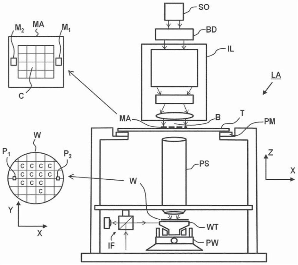
[0023] figure 1 A lithographic apparatus LA is schematically depicted. The lithographic apparatus LA compri...


PUM


Abstract

Disclosed is a method for obtaining a computationally determined interference electric field describing scattering of radiation by a pair of structures comprising a first structure and a second structure on a substrate. The method comprises determining a first electric field relating to first radiation scattered by the first structure; determining a second electric field relating to second radiation scattered by the second structure; and computationally determining the interference of the first electric field and second electric field, to obtain a computationally determined interference electric field.

Description

[0001] Cross References to Related Applications [0002] This application claims priority from European application 18186825.8 filed on 1 August 2018 and European application 18199813.9 filed on 11 October 2018, the entire contents of which are incorporated herein by reference. technical field [0003] The invention relates to a metrology or inspection device for determining properties of structures on a substrate. The invention also relates to a method for determining properties of structures on a substrate. Background technique [0004] A lithographic apparatus is a machine configured to apply a desired pattern onto a substrate. For example, lithographic equipment may be used, for example, in the manufacture of integrated circuits (ICs). A lithographic apparatus may, for example, project a pattern (also often referred to as a "design layout" or "design") at a patterning device (e.g., a mask) onto a radiation-sensitive material (anti- etchant) layer. [0005] To project...

Claims


Application Information

Patent Timeline
IPC IPC(8): G03F7/20
CPCG03F7/705G03F7/70633G01R31/2656G03F7/706839
Inventor P·A·J·廷尼曼斯帕特里克·华纳V·T·滕纳M·范德斯卡
Owner ASML NETHERLANDS BV
Learn More