
Image display system and method

a technology of image display and interchangeable components, which is applied in the field of image display systems and methods, can solve the problems of limiting the bulk and fragility of museum purchases, unable to describe an efficient method of displaying a selected image in the home or elsewhere, and unable to meet the requirements of a manufacturing business, etc., and achieves the effect of a viable manufacturing business

Inactive Publication Date: 2014-10-30
MUSEUM LIGHT
View PDF4 Cites 3 Cited by
  • Summary
  • Abstract
  • Description
  • Claims
  • Application Information

AI Technical Summary

Benefits of technology

[0012]An example of this invention is to create an efficient business model that serves the needs of museum gift shops and their customers so that exhibits visitors have seen in the museum may be enjoyed in the home after being appreciated in the museum. Many other markets besides museum gift shops can be served. Along the way, a viable manufacturing business is also created.

Problems solved by technology

Others arrive by public transportation such as a subway or bus, and therefore their carrying capability is limited.
Still others may visit a museum while on a distant trip; but they must return by air thereby limiting the bulk and fragility of their purchase at a museum shop.
Indeed, while the prior art teaches several approaches to the design of illuminated display units for displaying images or storing lampshade frames more compactly, none describe an efficient method to display a selected image in the home or elsewhere on an illuminated display unit that is comprised of compactly packaged interchangeable components.

Method used


Image

  • Image display system and method
  • Image display system and method
  • Image display system and method

Examples


Embodiment Construction

[0232]The present invention has broad applications to many fields for a variety of IDU's. For illustrative purposes only, a preferred mode for carrying out the invention is described herein.

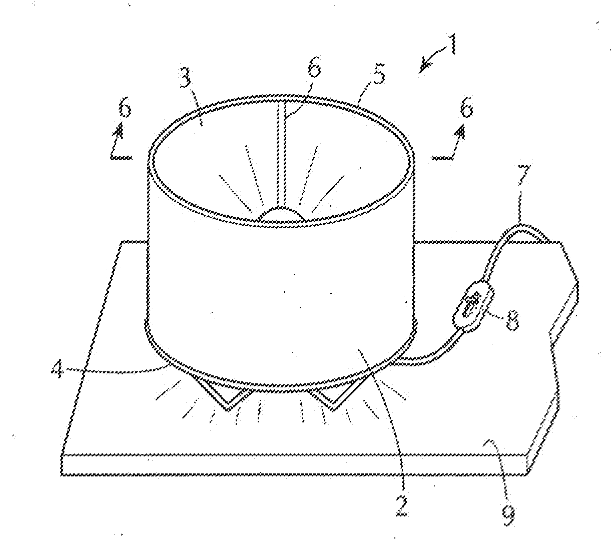
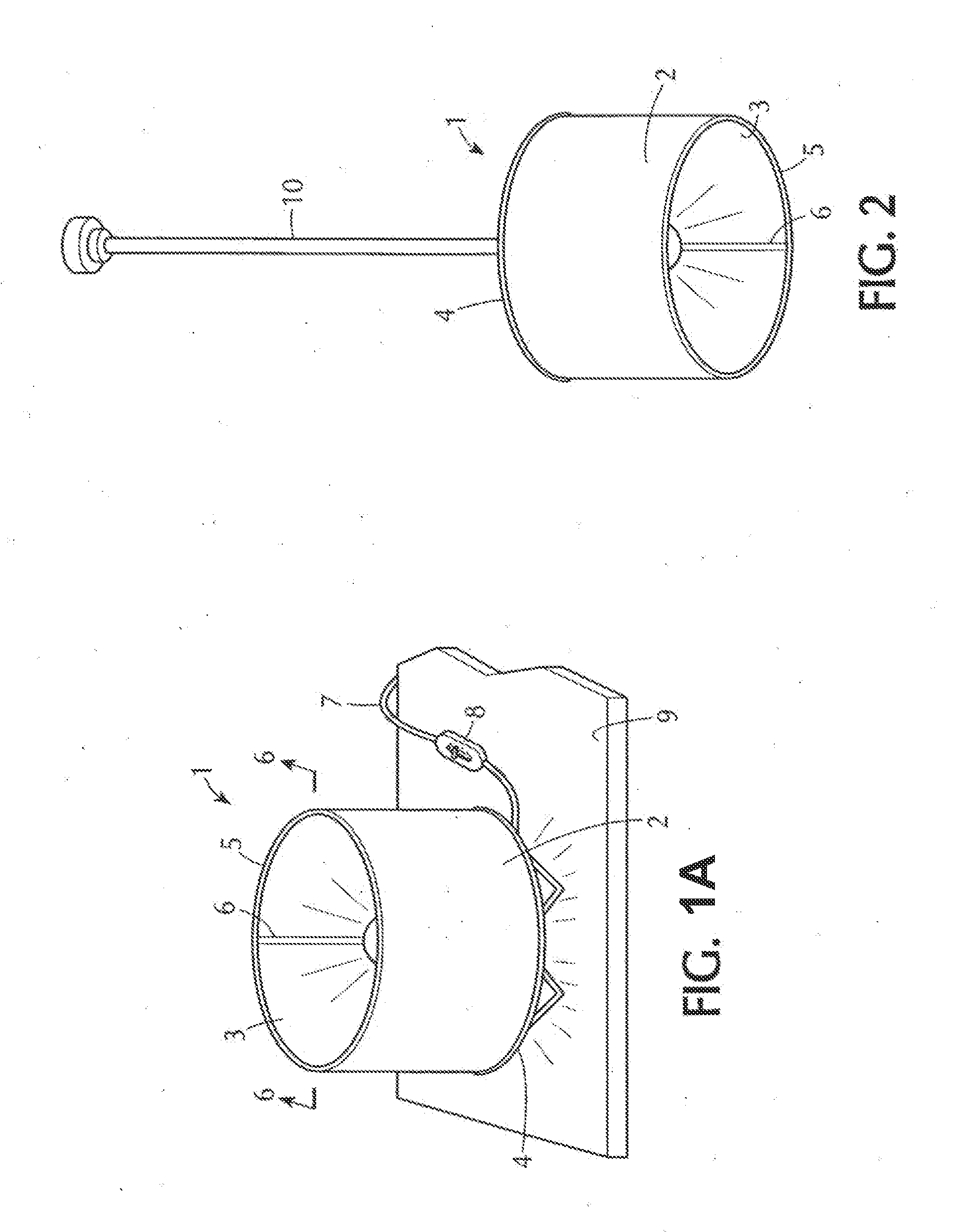
[0233]FIG. 1A shows a table top 9 on which illuminated display unit (IDU) 1 with image sheet 3 displaying image 2 rests. Image sheet 3 is contained and shaped between a support frame 4 at the bottom edge incorporating support legs facing down and a plain frame 5 at top edge. A small overlap 6 of the free ends is at the rear of the display unit. Electrical control (switch or switch / dimmer) 8 is shown on electrical line 7.

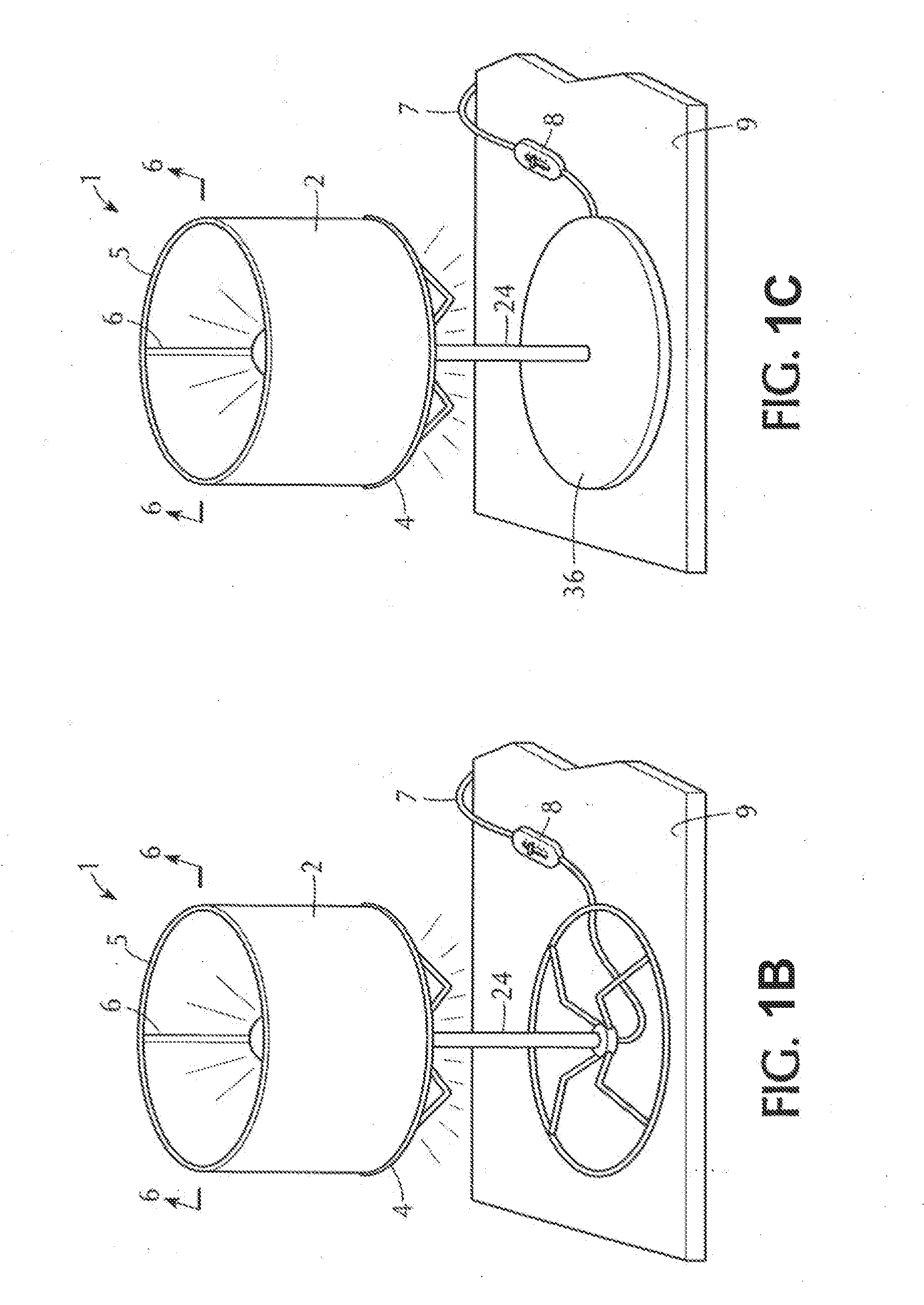
[0234]FIG. 1B is a similar image of the same IDU 1 but with a pedestal tube and second support frame added at the base, wherein the support legs extend upward within the region surrounded by image sheet 3 of the illuminated display unit (IDU) 1.

[0235]FIG. 1C is a similar image of the same IDU 1 but with a pedestal tube and with a modified base, also wherein the support legs extend...


PUM

PropertyMeasurementUnit
widthsaaaaaaaaaa
circumferenceaaaaaaaaaa
diameteraaaaaaaaaa

Abstract

An illumination device and shade for displaying a selected image in an illuminated display using fully assembled, partly assembled or ready to assemble components is provided for. The device allows for multiple mounting configurations and mounting options and provides for an easy to exchange image sheet.

Description

CROSS REFERENCE TO RELATED APPLICATIONS[0001]The present application is a Continuation of U.S. application Ser. No. 13 / 345,416 filed 6 Jan. 2012, which is a Continuation-in-Part of U.S. Ser. No. 12 / 802,486, filed 7 Jun. 2010, now abandoned, which is a Continuation-in-Part of U.S. application Ser. No. 12 / 653,126, filed 8 Dec. 2009 now U.S. Pat. No. 8,291,628 issued 23 Oct. 2012; each of which is incorporated herein by reference in its entirety.[0002]The present application also claims the benefit of priority to United Kingdom Application No. 1002334.9 filed 11 Feb. 2010, United Kingdom Application No. 1019865.3 filed 24 Nov. 2010, and European Application No. 10194003.6 filed on 7 Dec. 2010; each of which is incorporated herein by reference in its entirety.FIELD OF THE INVENTION[0003]The present invention relates to a method displaying a selected image in an illuminated display, using components sold fully assembled, partly assembled or ready to assemble in alternate configurations, ...

Claims


Application Information

Patent Timeline
Patent Type & Authority Applications(United States)
IPC IPC(8): G09F13/04F21V1/04
CPCF21V1/04G09F13/0413F21S6/002F21S6/004F21S6/005F21S8/06F21V1/00F21V1/06F21V1/22F21V17/007G09F13/04F21V1/02
Inventor ACWORTH, BRIANHERTH, GREG
Owner MUSEUM LIGHT
Learn More