Power supply system including panel with safety release

Active Publication Date: 2014-11-13
ATLANTIC DYNAMICS LLC
View PDF66 Cites 8 Cited by
  • Summary
  • Abstract
  • Description
  • Claims
  • Application Information

AI Technical Summary

Benefits of technology

The present invention provides a power supply system that is suitable for use with mobile systems. The system reduces the need for an engine or motor to supply energy to the mobile system when a power grid is available. It is designed to minimize unsafe use or operation of the system. The system includes a self-ejecting latch that ensures the power cord will release from the wall receptacle in a situation of neglect. The system is configured to ensure the power cord only pulls the cord at the plug / receptacle interface and not somewhere intermediate on the power cord itself. The power cord is securely connected to the mobile system so that it no longer active when disconnection occurs. The system also includes a complicated connector arrangement to ensure safety and prevent powered faulty connections or exposure to liquid or human contact. The invention provides access to power sources while minimizing or eliminating the need to operate an engine or motor and ensuring the safety of the system and users.

Problems solved by technology

Standard plug operations do not provide automatic power shutoff and breakaway protection.

Method used


Image

  • Power supply system including panel with safety release
  • Power supply system including panel with safety release
  • Power supply system including panel with safety release

Examples


first embodiment

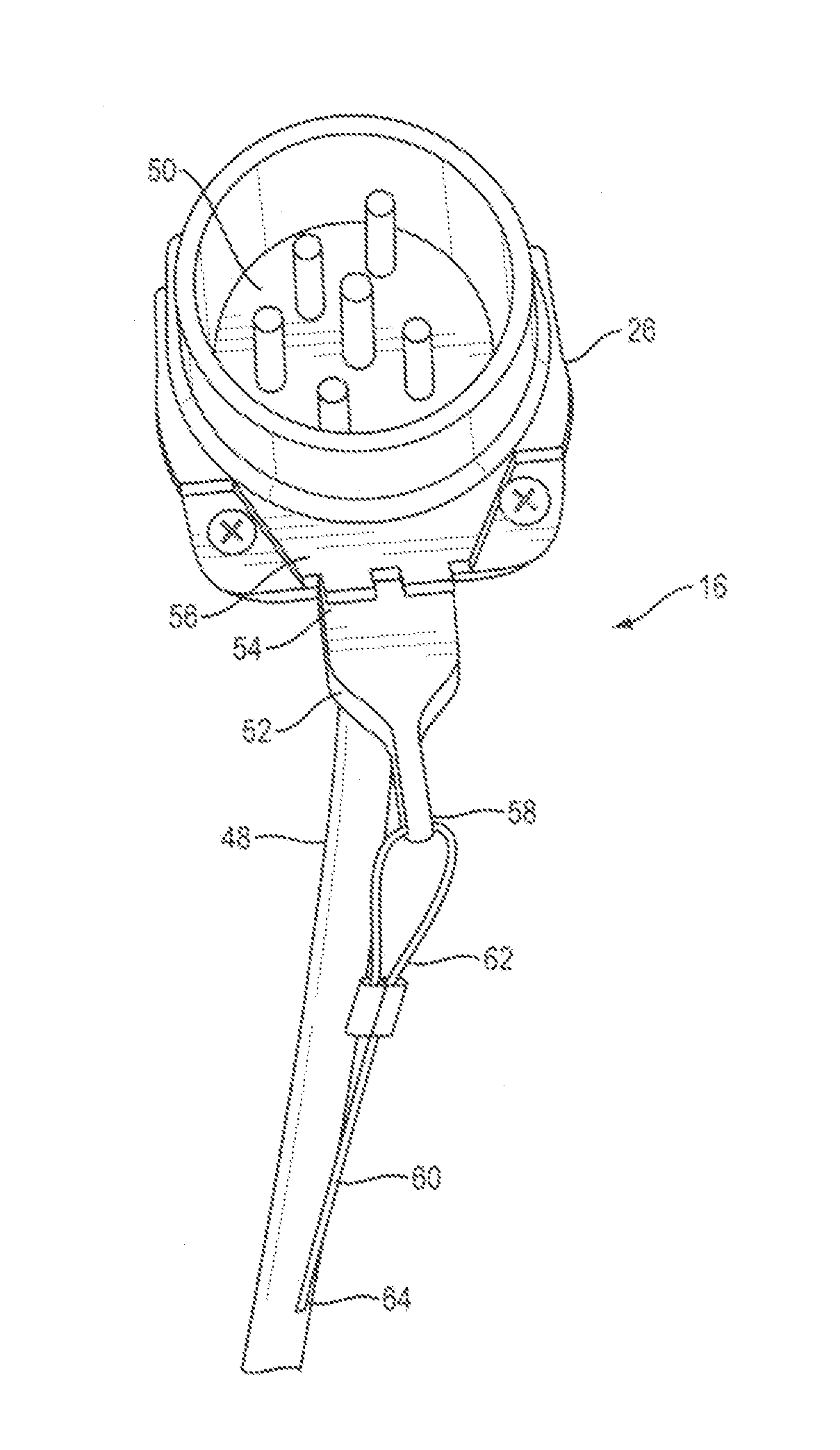
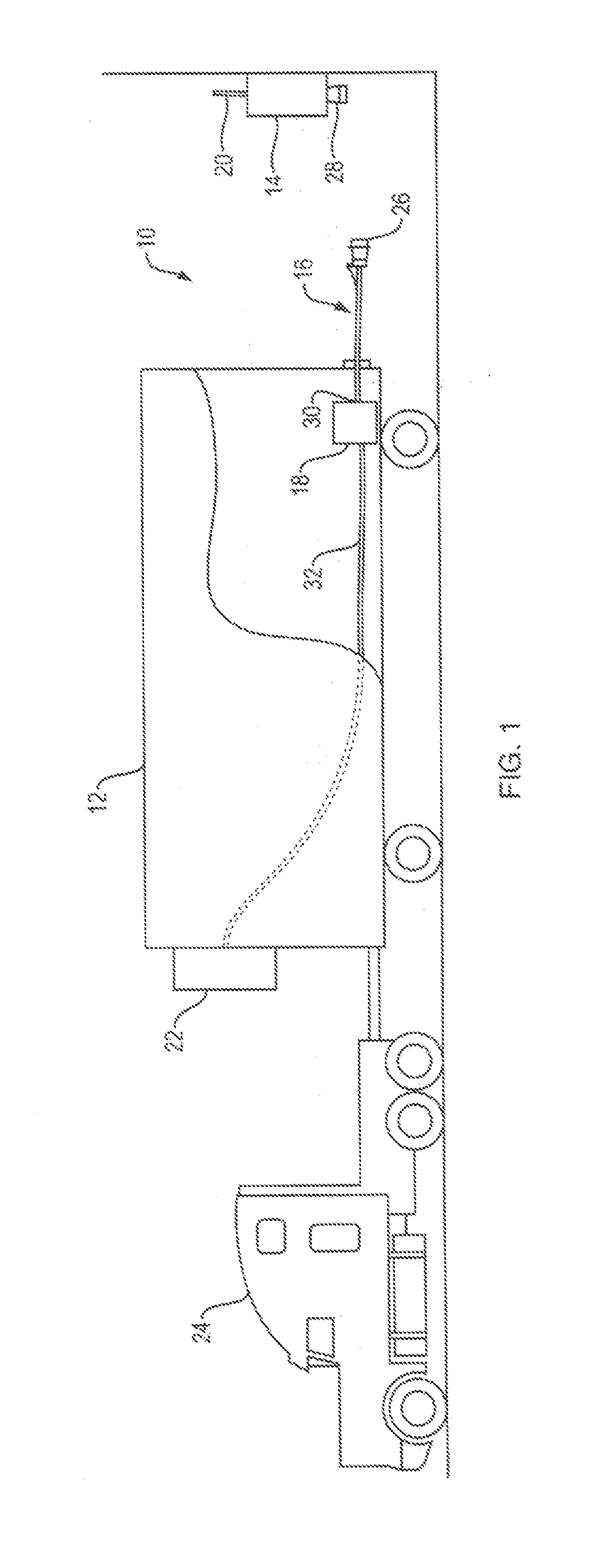
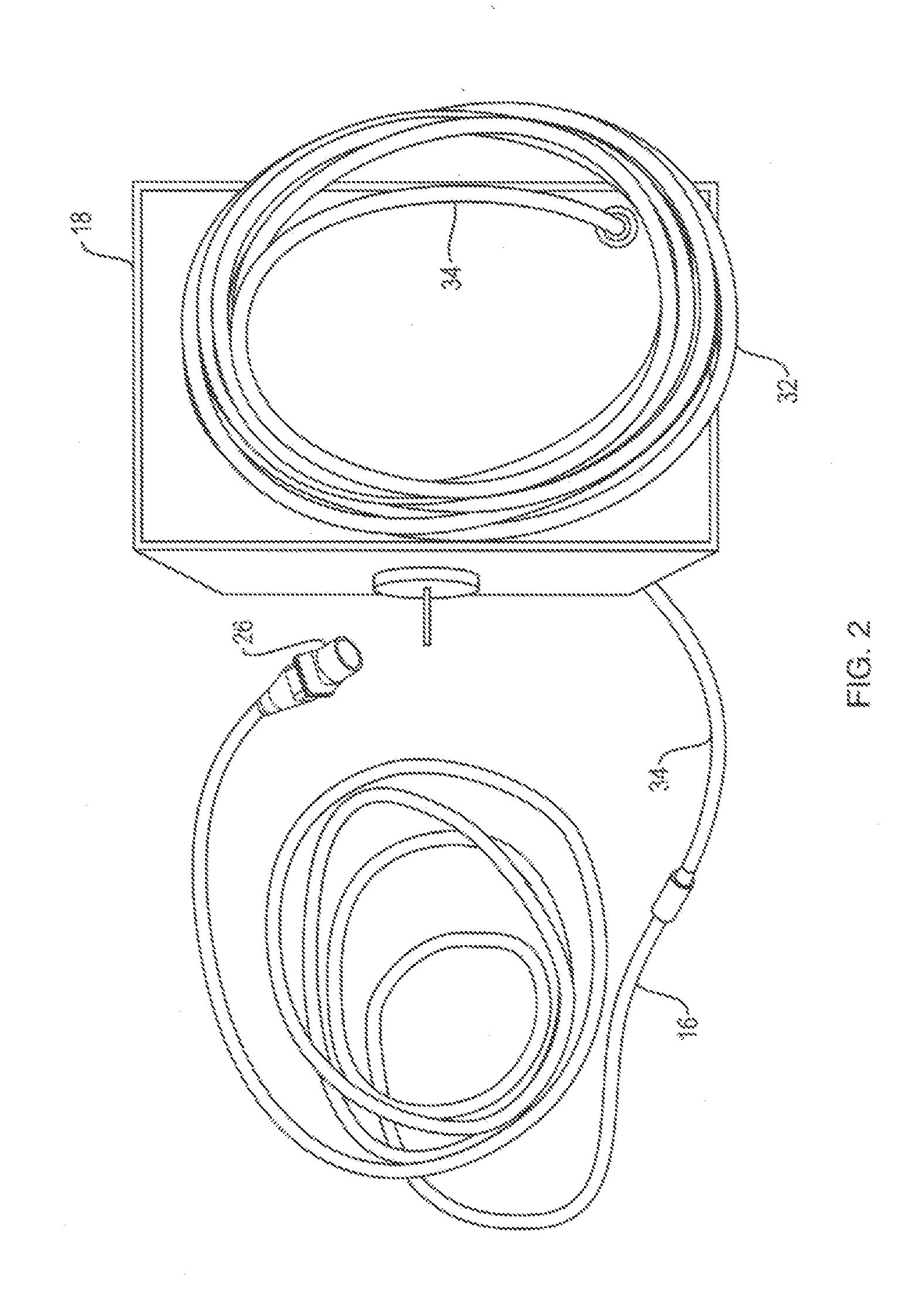
[0042]A power supply system 10 of the present invention is shown associated with a refrigerated trailer 12 in FIG. 1. The power supply system 10 includes a safety circuit panel 14, a power cord 16 and an optional cord storage box 18. The safety circuit panel 14 is coupled to grid power through panel cord 20, which provides electricity into the panel 14 for the purpose of connection to a power conductor, such as one or more wires of power cord 16. In the example usage represented in FIG. 1, the circuit panel 14 may be used to supply power to an engine of a refrigeration unit 22 of the trailer 12. In this way, the refrigeration unit 22 may be operated to keep the contents of the trailer 12 temperature controlled using grid power rather than power from the engine of the refrigeration unit 22, which itself must be powered by a tractor 24 used to haul the trailer 12. The power cord 16 includes a first end 26 for releasable connection to a wall receptacle 28 of the circuit panel 14 and a ...

second embodiment

[0054]A power supply system 100 of the present invention is shown associated with a refrigerated trailer 12 in FIG. 7. The power supply system 100 includes a safety circuit panel 114, a power cord 116 and a power plug 118 that may be contained in a containment box 119, shown in FIG. 9. The length of the power cord 116 is selectable. The power plug 118 is configured to ensure that current moves to the trailer 12 when it and the power cord 116 are aligned and connected in a specific way. In this embodiment, the power plug 118 includes a six-pin face that engages with a six-pinhole plug face 150 of the power cord 116. Current only moves when the two are properly aligned and engaged. The trailer 12 may include the optional cord storage box 18. The safety circuit panel 114 is coupled to grid power through panel cord 20, which provides electricity into the panel 114 for the purpose of connection to a power conductor, such as one or more wires of the power cord 116. In the example usage re...

third embodiment

[0064]A power supply system 200 of the present invention is shown associated with refrigerated trailer 12 in FIG. 15. The power supply system 200 includes a safety circuit panel 206, a remote control panel 214 and a power cord 16. An optional cord storage box 18 may be used as previously described with respect to the embodiment of the invention shown in FIG. 1. The safety circuit panel 206 is coupled to grid power through power supply cord 20′, which provides electricity into the panel 206. Safety circuit panel 206 is connected to remote control panel 214 by control cord 220 for the purpose of connection to a power conductor, such as one or more wires of power cord 16. In the example usage represented in FIG. 15, the safety circuit panel 206 may be used to supply power to an engine of refrigeration unit 22 of the trailer 12.

[0065]The power cord 16 includes first end 26 for releasable connection to wall receptacle 28 of the remote control panel 214, which receives power from safety c...


PUM


Abstract

A power supply system for use with a power source. The system includes one or more power supply connections and an optional configuration with one or more remote control panels spaced from a safety circuit panel. The safety circuit panel includes a safety circuit. The system further includes a power cable with a safety ejector subsystem. The safety ejector subsystem includes a latch connected to the wall receptacle connector of the power cable and a tension line connected to the latch and to the power cable. When the power cable is placed in tension, such as when the power cable has not been disconnected from the wall receptacle in the ordinary way, the safety ejector subsystem forces the disconnection of the power cable from a plug, thereby ensuring that no live wiring is exposed to the environment.

Description

CROSS REFERENCE TO RELATED APPLICATIONS[0001]This application is a continuation-in-part of, and claims a priority benefit to, pending U.S. patent application Ser. No. 13 / 759,432, filed Feb. 5, 2013, entitled POWER SUPPLY SYSTEM INCLUDING PANEL WITH SAFETY RELEASE, which is a continuation-in-part of, and claims the priority benefit to, U.S. patent application Ser. No. 13 / 631,294, filed Sep. 28, 2012, entitled POWER SUPPLY SYSTEM INCLUDING PANEL WITH SAFETY RELEASE, which is a nonprovisional of, and claims a priority benefit to, U.S. provisional patent application Ser. No. 61 / 752,044, filed Jan. 14, 2013, entitled POWER SUPPLY SYSTEM INCLUDING PANEL WITH SAFETY RELEASE. The applications are owned by a common assignee. The priority applications are incorporated in their entirety herein by reference.BACKGROUND OF THE INVENTION[0002]1. Field of the Invention[0003]The present invention relates power supply systems including supply panels. More particularly, the present invention relates t...

Claims


Application Information

Patent Timeline
IPC IPC(8): H01R13/633B60L11/18B60D1/64
CPCH01R13/633B60D1/64B60L11/18H01R13/6275H01R2201/26H02J2310/40B60L3/04H02J7/00
Inventor LAMB, SCOTT D
Owner ATLANTIC DYNAMICS LLC
Why Eureka
Try Eureka