Turbomachine rotor blade

Active Publication Date: 2015-01-22
SN DETUDE & DE CONSTR DE MOTEURS DAVIATION S N E C M A
View PDF9 Cites 16 Cited by
  • Summary
  • Abstract
  • Description
  • Claims
  • Application Information

AI Technical Summary

Benefits of technology

[0035]With this optimized shape for the outer part, it is easier during fabrication of the blade to position the center of gravity of the outer part correctly relative to the center of gravity of the inner part of the airfoil. It is generally sought to align these two centers of gravity along the radial direction. Positioning the center of gravity of the outer part better relative to the center of gravity of the root part of the airfoil

Problems solved by technology

A first problem encountered with such blades 10 stems from the fact that when the second portions 21B, 22B of the outer part 14 are narrow (i.e. present limited height along the stacking axis X), it is difficult to deposit the anti-wear material on these portions 21B, 22B only (i.e. it is difficult to avoid overflowing from these portions), given that the deposition method used is not sufficiently accurate.
Unfortunately, depositing anti-wear material outside the portions 21B,

Method used


Image

  • Turbomachine rotor blade
  • Turbomachine rotor blade
  • Turbomachine rotor blade

Examples


Example

[0055]Embodiments of a rotor blade with an outer part are described in detail below with reference to the accompanying drawings. These embodiments illustrate the characteristics and advantages of the invention. It should nevertheless be recalled that the invention is not limited to these embodiments.

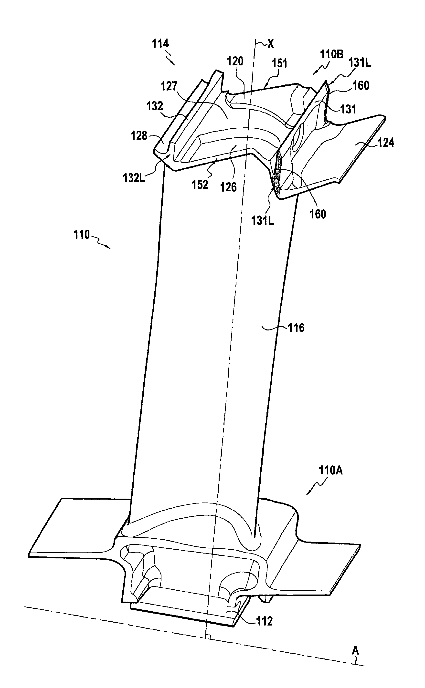
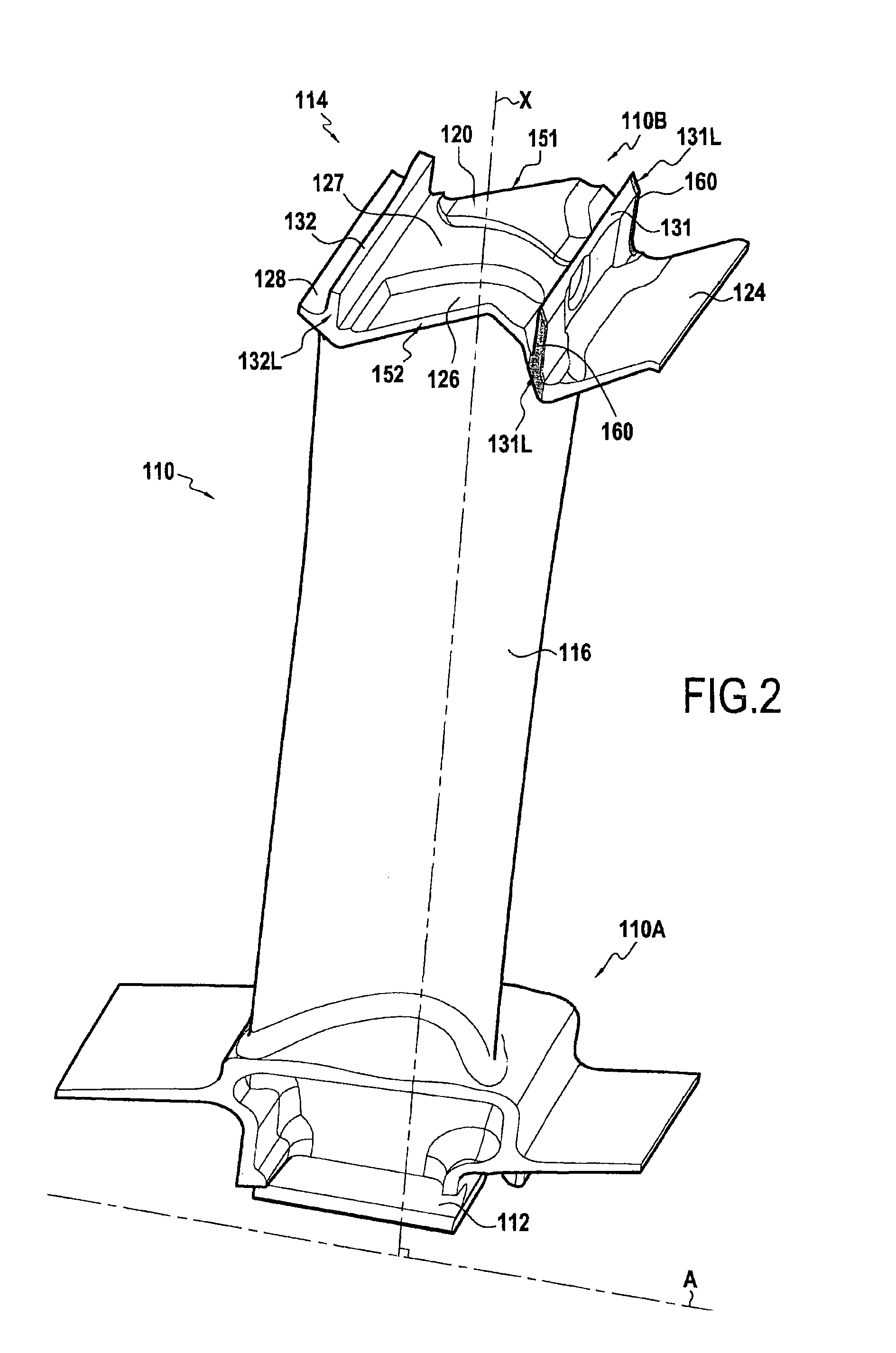
[0056]FIG. 2 shows an embodiment of a turbomachine rotor blade 110. Such a blade may be used in a low pressure stage of an airplane turbojet.

[0057]The rotor blade 110 comprises an airfoil 116 extending along the stacking axis X of the blade between the proximal and distal ends 110A and 110B of the blade (i.e. its inner and outer ends). At its proximal end 110A, the blade has a root 112 whereby it is fastened to a rotor disk (not shown) of a turbomachine (not shown). This disk rotates about the axis A of the engine. At its distal end 110B, the blade 110 has an outer part 114.

[0058]When a plurality of rotor blades 110 are fastened to a rotor disk, their outer parts 114 are arranged side by...


PUM


Abstract

A turbomachine rotor blade presenting an outer part (314) at its distal end (310B), the outer part comprising a platform (320) defining the outside surface of the passage for gas passing through the turbomachine and presenting first (351) and second opposite side edges; and upstream and downstream sealing wipers (331, 332) extending outwards from said platform (320), each wiper extending between two lateral faces (331L, 332L) situated respectively at the first (351) and second side edges. The lateral faces (331L, 332L) of the upstream and downstream wipers (331, 332) are covered at least in part in an anti-wear material (360).

Description


Claims


Application Information

Patent Timeline
Owner SN DETUDE & DE CONSTR DE MOTEURS DAVIATION S N E C M A
Why Eureka
Try Eureka