Direct vision cryosurgical probe and methods of use

Inactive Publication Date: 2015-01-29
ARRINEX INC
View PDF12 Cites 48 Cited by
  • Summary
  • Abstract
  • Description
  • Claims
  • Application Information

AI Technical Summary

Benefits of technology

[0035]An additional object of this invention is a method for cryosurgical ablation of the function of a nerve comprising inserting a cryosurgical probe between the target nerve and the artery and vein associated with the nerve; with the cryosurgical probe having an elongated structure with a distal end, a proximal end, and at least one central lumen; with said distal end comprising an outer inflatable balloon structure configured as an optical imaging window, and as a tissue dilator enclosing at least one optical imaging device, at least one inner cryogenic evaporator balloon, and at least one inner thermal insulation balloon; with said proximal end comprising a means for introducing a liquid refrigerant into the cryogenic evaporator balloon through a central lumen, a means of removing evaporated refrigerant from the cryogenic evaporator balloon through a central lumen at a predetermined pressure, a means for inflating the

Problems solved by technology

However, proper positioning of the cooling probe relative to the tissue may be difficult to achieve d

Method used


Image

  • Direct vision cryosurgical probe and methods of use
  • Direct vision cryosurgical probe and methods of use
  • Direct vision cryosurgical probe and methods of use

Examples


Embodiment Construction

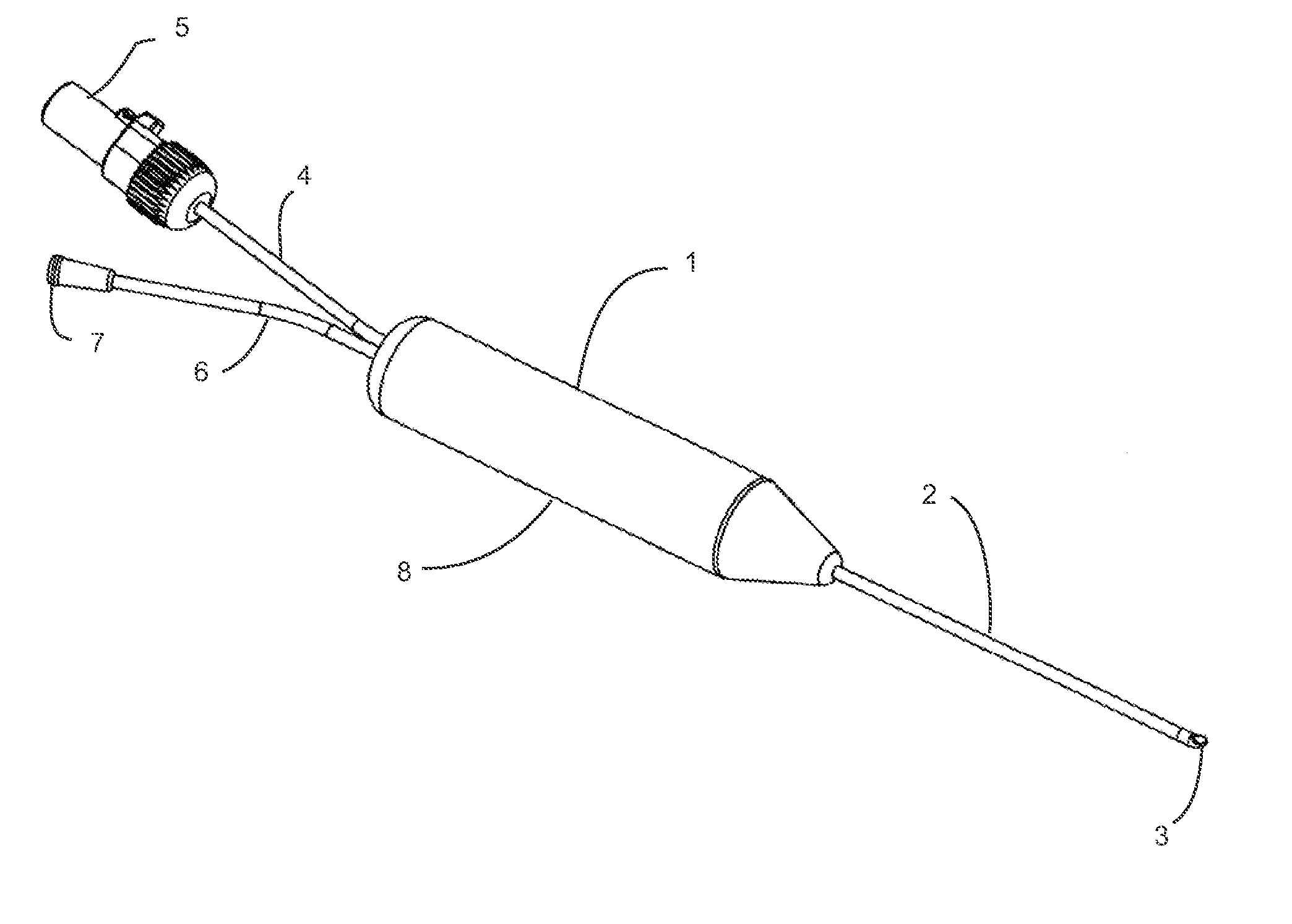
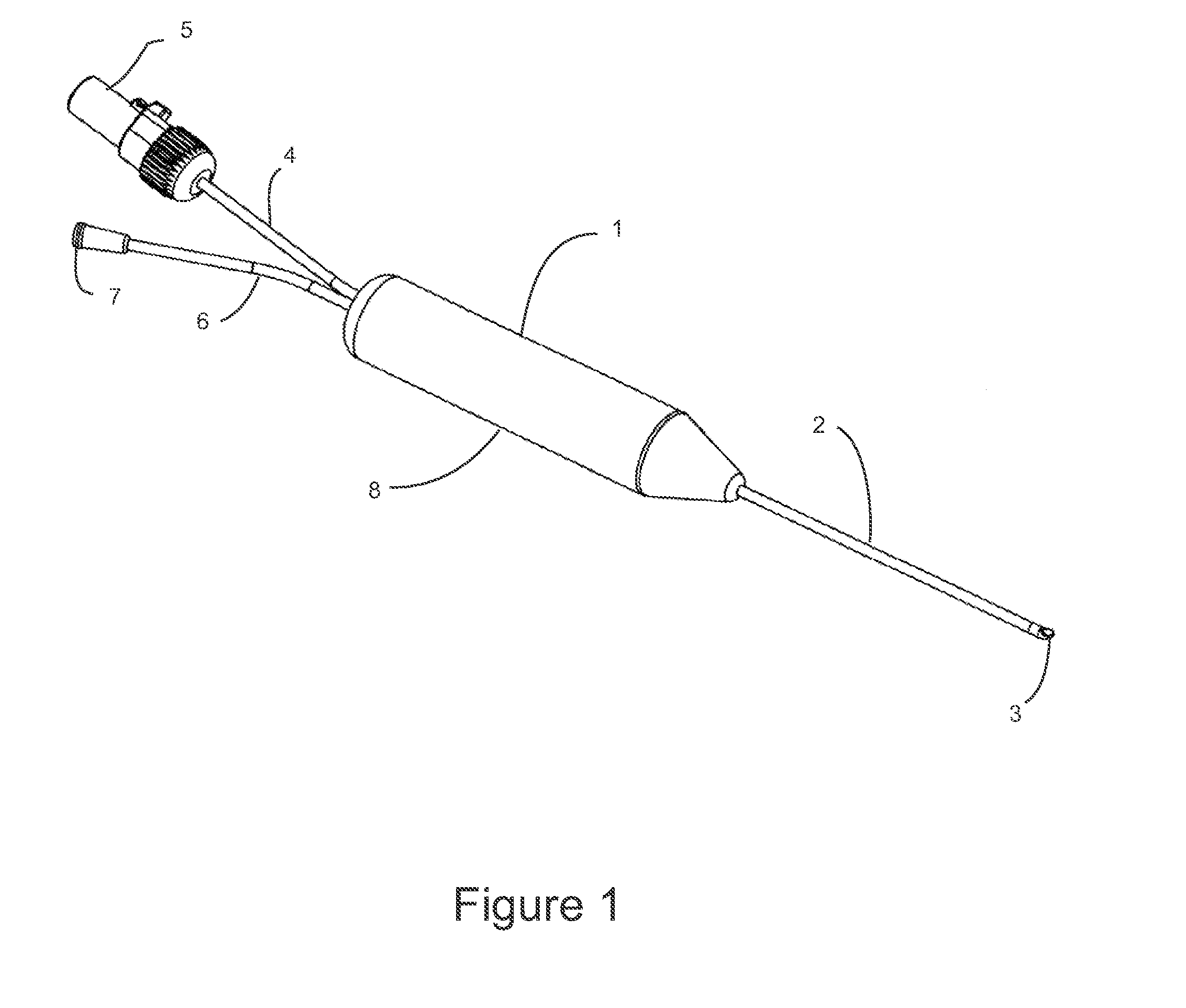
[0056]FIG. 1 is an illustration of the central embodiment of surgical imaging probe 1 configured for accessing a distal surgical site within a patient by advancement between anatomical structures by atraumatic blunt dissection using image guidance for the purpose of performing a cryosurgical step. Surgical imaging probe 1 comprises probe shaft 2, non-coring optically transparent needle tip 3, probe handle 8, electrical lead 4, electrical connector 5 fluid tube 6 and fluid connector 7. Probe shaft 2 is between approximately 5 and 20 centimeters long, and between approximately 2.5 and 3.5 millimeters in diameter. Probe shaft 2 has a central lumen between approximately 2.3 and 3.3 millimeters in diameter. Probe shaft 2 may be fabricated from a stainless steel hypodermic tube, or may be fabricated from another metal used in surgical instruments such as titanium. Probe shaft 2 is substantially rigid and is capable of transmitting lateral, longitudinal, and torsional forces along its leng...


PUM


Abstract

A direct vision cryosurgical and methods of use are described herein where the device may generally comprise an elongated rigid structure with a distal end, a proximal end, and a central lumen. The distal end may comprise a non-coring optically transparent needle tip with at least one lateral fenestration in communication with the central lumen. The distal end may also house at least one imaging device configured for distal imaging. A proximal end of the device may comprise a handle with a means for connecting the imaging device(s) to an imaging display(s), and a means for accessing bodily tissue in the vicinity of the distal end with a cryo-ablation probe through the central lumen and the lateral fenestration(s) for diagnostic or therapeutic purposes.

Description

CROSS-REFERENCE TO RELATED APPLICATIONS[0001]This application claims priority to U.S. Prov. Pat. App. 61 / 858,104 filed Jul. 24, 2013, which is incorporated herein by reference in its entirety.FIELD OF THE INVENTION[0002]The present invention relates to cryosurgical probes and their methods of use. More particularly, the present invention relates to cryosurgical probes which are configured to be advanced into a body lumen while providing for direct visualization.BACKGROUND OF THE INVENTION[0003]Accessing and treating regions within a body lumen such as the nasal cavities are often performed by utilizing a probe which is cooled via a chilled fluid, a cryo-fluid such as Nitrous Oxide, or through some other cooling mechanism. The cooled tip can be placed into contact against the tissue region to be treated. However, proper positioning of the cooling probe relative to the tissue may be difficult to achieve due to a number of factors such as limited space, lack of visual contact, anatomic...

Claims


Application Information

Patent Timeline
IPC IPC(8): A61B18/02A61B1/05A61B1/00A61B1/313
CPCA61B18/0218A61B1/3132A61B1/05A61B2018/0293A61B1/00082A61B2018/0212A61B1/00087A61B18/02A61B2018/00577A61B2018/00982A61B2018/0262A61B1/00177A61B1/00179A61B1/018A61B1/0615A61B1/0623A61B1/233A61B1/00042A61B1/00183
Inventor SAADAT, VAHIDHERRON, MATTHEWEWERS, RICHARD C.
Owner ARRINEX INC
Why Eureka
Try Eureka