Catheter system with movable sleeve

Inactive Publication Date: 2015-02-26
BIOTRONIK
View PDF3 Cites 28 Cited by
  • Summary
  • Abstract
  • Description
  • Claims
  • Application Information

AI Technical Summary

Benefits of technology

[0055]With a method of this type, the exact positioning of the stent, in particular of the stent with the artificial heart valve, is key. Here, the advantages of the present invention are particularly relevant. Due to the hydraulic transmission of force as the sleeve is moved by means of expansion of a balloon, the release of the self-expanding stent can be controlled very accurately and precisely. In particular, the embodiment of the invention with at least one first balloo

Problems solved by technology

These high frictional forces and the application of force necessary on the part of the operator hinder the accurately positioned release of the stent.
The catheter system d

Method used


Image

  • Catheter system with movable sleeve
  • Catheter system with movable sleeve
  • Catheter system with movable sleeve

Examples


Example

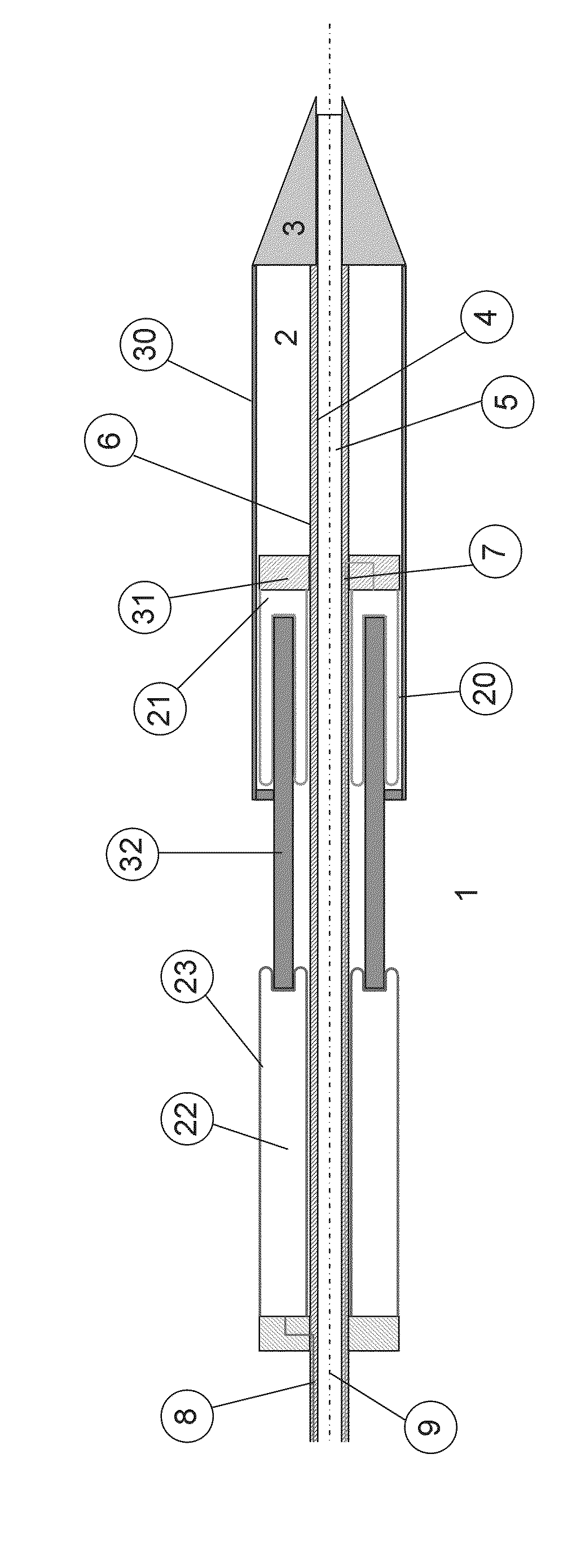
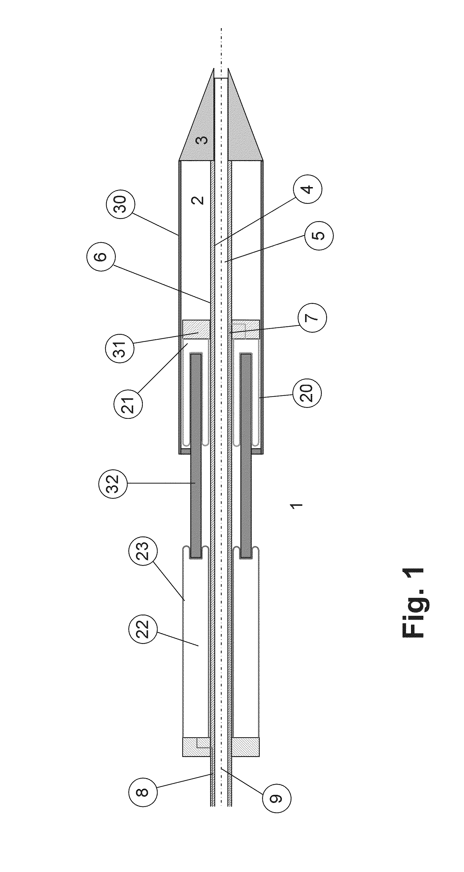
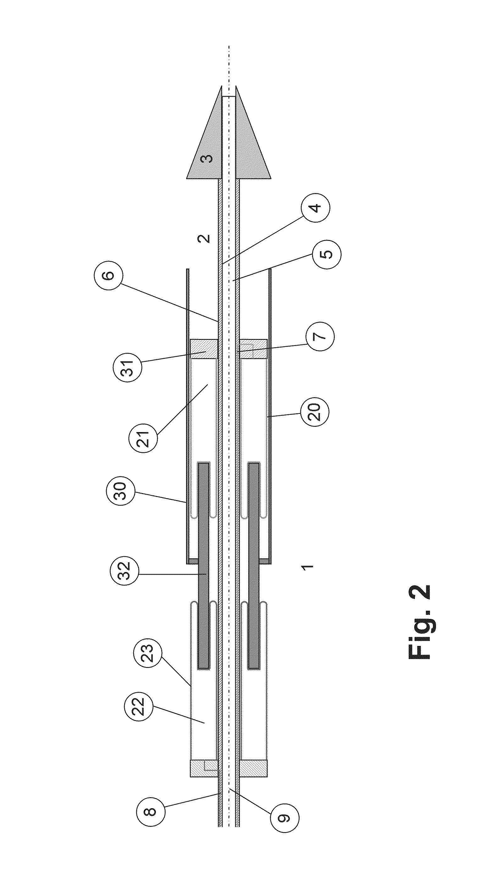
[0063]Here, only the distal part of the exemplary embodiment is illustrated in the figures.

[0064]FIG. 1 shows an exemplary embodiment of a catheter system according to the invention in the state for introduction of the catheter 1 into the bodily vessel. The self-expanding stent, for example a self-expanding stent having an artificial heart valve, is located in the cavity 2 and is covered completely by the sleeve 30. The sleeve 30 prevents the stent from expanding. The stent remains in the compressed state and thus has a slightly smaller diameter than the catheter 1 itself and can thus be inserted with the catheter 1 into the bodily vessel.

[0065]The catheter 1 has an inner shaft 4, which surrounds the first, inner lumen 5. The inner lumen 5 is generally used to receive the guide wire. The catheter shaft 6 itself is formed as a shaft having three different lumens, the illustrated inner lumen 5 for the guide wire and the outer, second lumen 7 and the outer third lumen 8 (neither of whi...


PUM


Abstract

A catheter system for inserting a self-expanding stent into a bodily vessel. The catheter (1) has a movable sleeve (30), which holds the self-expanding stent in the space (2) when being positioned in the bodily vessel. As the self-expanding stent is released, the sleeve is pushed back by means of the application of fluid to the balloon (20). Here, the movable sleeve (30) can be moved proximally or distally in a precise manner by adjusting the pressure ratio in the balloons (20, 23). A controlled release and renewed capture of the self-expanding stent are possible accordingly.

Description

CROSS REFERENCE TO RELATED APPLICATIONS[0001]This invention claims priority to U.S. provisional patent application Ser. No. 61 / 867,626 filed Aug. 20, 2013; the entire content of which is herein incorporated by reference in its entirety.TECHNICAL FIELD[0002]The invention relates to a catheter system suitable for insertion into a bodily vessel, comprising a catheter having a functional component and a movable sleeve in a distal region, wherein a diameter of the sleeve corresponds at least to the diameter of the functional component and a length of the sleeve is greater than the length of the functional component, further wherein the sleeve covers the functional component when the catheter system is in a state for introduction of the catheter into the bodily vessel, further wherein the catheter at least in the distal region has a shaft having a first, inner lumen and an outer, second lumen.[0003]BACKGROUND[0004]Catheters, in particular wire-guided catheters, are used broadly in predomi...

Claims


Application Information

Patent Timeline
IPC IPC(8): A61F2/966A61F2/24A61F2/82
CPCA61F2/966A61F2/82A61F2/958A61F2/2436A61F2/24A61F2250/0003
Inventor HEPKE, MARKUSWESSELMANN, MATTHIASECKERMANN, FABIAN
Owner BIOTRONIK
Why Eureka
Try Eureka