Finite time sliding mode control system and method for bridge crane system under limited control input

A finite time and control method technology, applied in general control systems, control/regulation systems, adaptive control, etc., can solve the problem of weak robustness of sliding mode control, infinite time convergence, and solve the difficulty of implementation and the impact of implementation effects. It is difficult to obtain the expected effect and other problems, to achieve the effect of improving control robustness, strengthening connection, and weakening system chattering

Active Publication Date: 2021-02-12
中国人民解放军火箭军工程大学
View PDF3 Cites 2 Cited by
  • Summary
  • Abstract
  • Description
  • Claims
  • Application Information

AI Technical Summary

Problems solved by technology

[0005] For the bridge crane system, the driving force of the system cannot be infinite, and the control system must be able to achieve effective control within a bounded range, that is, considering the saturated nonlinear characteristics of the actuator in actual engineering. Therefore, it is necessary to design a system that considers input saturation, The control method with limited control can achieve stable control on the basis of achieving faster anti-swing speed as much as possible; secondly, based on the problems of weak robustness and infinite time convergence of traditional sliding mode control, a fast terminal is introduced Sliding mode control; in addition, it is necessary to consider the complexity of the structural design of the sliding mode controller based on the traditional fast terminal. On the one hand, it solves the problem of separately processing the angle information and the trolley position error information when the sliding It is difficult to obtain the expected effect in the system with inaccurate measurement of system feedback, and solve the problem of difficulty in realization and effect on the effect of realization

Method used


Image

  • Finite time sliding mode control system and method for bridge crane system under limited control input
  • Finite time sliding mode control system and method for bridge crane system under limited control input
  • Finite time sliding mode control system and method for bridge crane system under limited control input

Examples


Embodiment Construction

[0065] The present invention will be described in further detail below in conjunction with the accompanying drawings.

[0066] A kind of limited time sliding mode control method of bridge crane system provided by the present invention comprises the following steps:

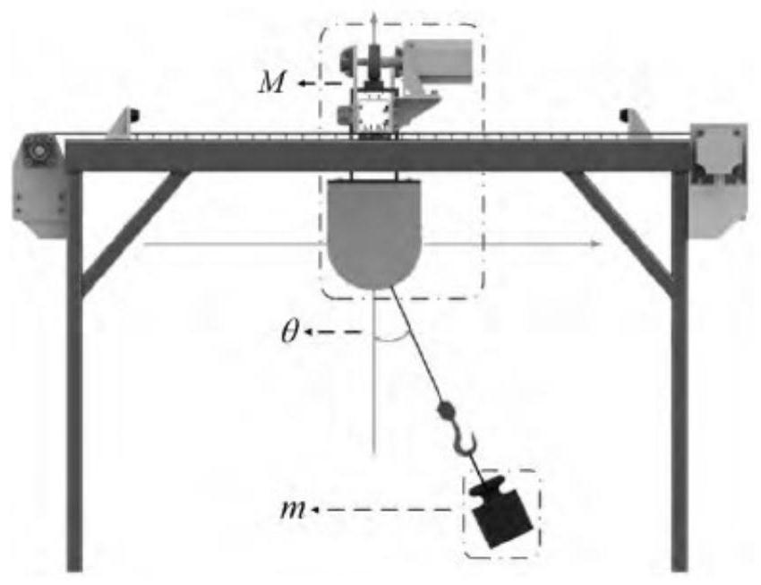
[0067] Step 1. Determine the control target of the bridge crane system, where the bridge crane system is two-dimensional underactuated, and the schematic diagram of the two-dimensional underactuated bridge crane system is as follows figure 1 shown;

[0068] The two-dimensional underactuated bridge crane system is represented by formula (1), and the system state error vector is defined e =[e 1 ,e 2 ,e 3 ,e 4 ] T ; e i =x i -x di ; x di For the control target, i=1,2,3,4:

[0069]

[0070] in, x =[x 1 ,x 2 ,x 3 ,x 4 ] T is the system state vector, respectively representing the trolley position, speed, load deflection angle and angular velocity; u(t) is the control input; Δ 1 ,Δ 2 is an uncertain...


PUM


Abstract

The invention provides a finite time sliding mode control system and method for a bridge crane system under a limited control input. The method comprises the following steps: 1, determining a controltarget of a two-dimensional under-actuated bridge crane system; step 2, according to the control target obtained in the step 1, constructing a total sliding mode surface of the system in combination with a hierarchical sliding mode theory; 3, constructing a total control law of the system according to the total sliding mode surface of the system obtained in the step 2; and 4, constructing a control-limited fast terminal sliding mode controller according to the total control law of the system obtained in the step 3. The method provided by the invention has two control effects, can provide a basis for rapid anti-swing and accurate and effective positioning control of the bridge crane system under various complex conditions, and enables the bridge crane system to be better applied to variousindustrial fields.

Description

technical field [0001] The invention belongs to the control technology of an underactuated system, and mainly relates to a limited-time sliding mode control system and method of a bridge crane system with limited control input. Background technique [0002] As a common indoor transfer equipment, bridge cranes are widely used in petrochemical, aerospace, military, mining and metallurgy, food and medicine, garbage disposal and other places. However, because the bridge crane is a flexible body such as a rope, the system belongs to a type of underactuated system. Although it can make the crane structure light and increase the lifting capacity, it will also bring negative effects, such as the crane load swing, which cannot be fast and stable. Lifting cargo, etc. For this reason, the main goal of bridge crane control is to complete the fast and accurate transfer of loads in the shortest possible time, which involves two major problems: accurate positioning of the trolley and rapi...

Claims


Application Information

Patent Timeline
Patent Type & Authority Applications(China)
IPC IPC(8): G05B13/04
CPCG05B13/042
Inventor 何祯鑫王欣刘春桐王兆强王杰强宝民魏小玲
Owner 中国人民解放军火箭军工程大学
Why Eureka
Try Eureka