Power supply circuit for driving LED lamp and power supply method, and primary-side control circuit of flyback transformer

a technology of power supply circuit and power supply method, which is applied in the direction of process and machine control, electric variable regulation, instruments, etc., can solve the problems of flicker, color change, and inability to meet the design or cost requirements of ac-dc converters with the aforementioned two-stage structure for indoor electric lights, and achieves stable link voltage and reduces the output current of the flyback converter

Active Publication Date: 2015-05-21
SILICON WORKS CO LTD
View PDF5 Cites 18 Cited by
  • Summary
  • Abstract
  • Description
  • Claims
  • Application Information

AI Technical Summary

Benefits of technology

[0018]Consequently, according to the present invention, ripple components existing in the output of the boost power factor correction converter can be reduced by the valley fill circuit, and an input voltage with reduced ripples is provided to the primary side of the flyback converter, so that ripples of an output current of the flyback converter i

Problems solved by technology

In an illumination field, an existing illumination apparatus using a fluorescent lamp or a mercury lamp has been replaced with an LED lamp due to energy inefficiency.
Therefore, the AC-DC converter having the aforementioned two-stage structure is not suitable for low power applications such as indoor electric lights in terms of design or cost.
However, in the AC-DC converter of the aforementioned single-stage structure, capabil

Method used


Image

  • Power supply circuit for driving LED lamp and power supply method, and primary-side control circuit of flyback transformer
  • Power supply circuit for driving LED lamp and power supply method, and primary-side control circuit of flyback transformer
  • Power supply circuit for driving LED lamp and power supply method, and primary-side control circuit of flyback transformer

Examples


Embodiment Construction

[0027]Hereafter, exemplary embodiments of the present invention will be described in detail with reference to the accompanying drawings.

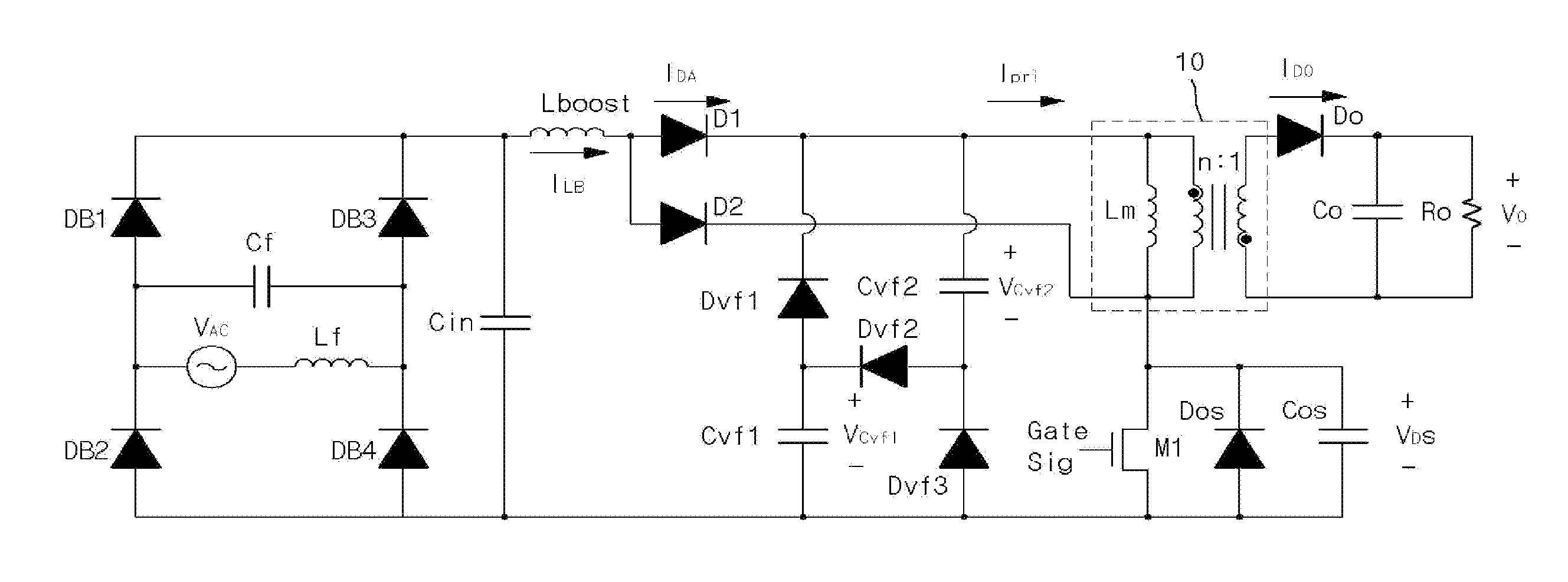
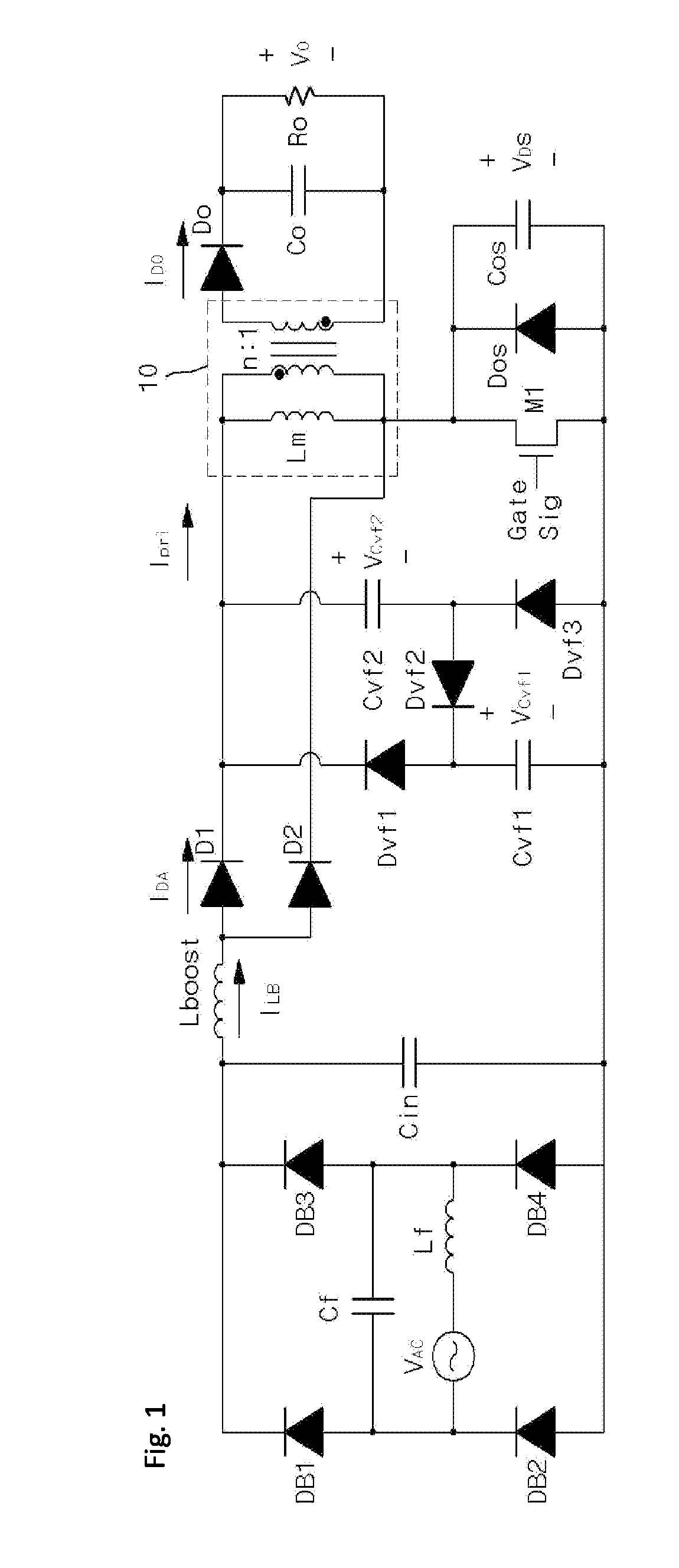
[0028]An embodiment according to the present invention may have a configuration as illustrated in FIG. 1. The embodiment of FIG. 1 has a two-stage structure including a boost power factor correction converter that performs first power factor correction with a first DCM and provides a boost current (ILB) and a flyback Dc-DC converter that performs second power factor correction with a second DCM.

[0029]The boost power factor correction converter includes a rectification circuit that outputs a rectified voltage and a boost inductor (Lboost) that receives the output of the rectification circuit and provides the boost current (ILB).

[0030]The rectification circuit includes an AC power source (VAC), a filter inductor (Lf) serially connected to the AC power source (VAC), a filter capacitor (Cf) connected in parallel with the AC power source (VAC) and the fi...


PUM


Abstract

The present invention discloses a power supply circuit for driving an LED lamp and a power supply method. The power supply circuit is constituted by an AC-DC converter by adopting DCM-DCM. Also, the power supply circuit adopts a valley fill circuit to reduce rippling of output current and adopts the DCM-DCM to stabilize a link voltage, thereby realizing a power factor correction circuit having two-stage structures. Thus, an input voltage of the flyback converter may be improved, and a high reverse voltage may be applied.

Description

TECHNICAL FIELD[0001]The present disclosure relates to a power circuit, and more particularly, to a power circuit for driving an LED lamp, a method for supplying power to the LED lamp by using a valley fill circuit, and a primary side control circuit of a flyback transformer that performs DC-DC converting.BACKGROUND ART[0002]Recently, in order to improve resource exhaustion and environmental issues, various methods for increasing the efficiency of an electric apparatus have been spotlighted.[0003]In an illumination field, an existing illumination apparatus using a fluorescent lamp or a mercury lamp has been replaced with an LED lamp due to energy inefficiency. The LED lamp is required to have a high power factor in order to increase the energy efficiency.[0004]A conventional AC-DC converter for driving an LED lamp may have a two-stage structure employing a boost converter and a flyback converter in order to obtain a high power factor. The boost converter is provided for power factor...

Claims


Application Information

Patent Timeline
IPC IPC(8): H02M3/335H02M1/42H05B33/08H05B44/00
CPCH02M3/33507H02M1/42H05B33/0818H02M1/14H02M1/4258H05B45/382H05B45/38H05B45/355Y02B70/10H05B47/10H05B45/385Y02B20/30
Inventor HONG, JU PYOKIM, JUN HO
Owner SILICON WORKS CO LTD
Why Eureka
Try Eureka